RFID reader on a Raspberry Pi
Inexpensive components for the SPI interface let you upgrade a Raspberry Pi 4 to a display system for zero-contact RFID-based data acquisition.
Radio-frequency identification (RFID) tags have become indispensable in industry and government, as well as the wholesale and retail spaces. The inexpensive transponder chips can be found on clothing labels, identification cards, and credit cards. Armed with just a Raspberry Pi and an RFID kit, you can read the data from these chips and view it on a display.
In this project, I read serial numbers from RFID tags stuck on 3D-printed pumpkins – a slightly different kind of detection task. To do this, I connect an RC522 RFID kit and a 1.8-inch ST7735 serial peripheral interface (SPI) thin-film transistor (TFT) display to a Raspberry Pi 4. Together, the two modules can cost less than $15 (EUR15, £14) in online stores. The pumpkins contain simple RFID tags, also available for very little cash. Although at first glance the project seems clear-cut and sounds as if it should work right away, check out the “Mishaps, Misfortunes, and Breakdowns” box to find out what can go wrong.
After some brief research, I decided which libraries I was going to use to control the modules. After a day of pondering and programming, it turned out that the library for the RFID reader had not been maintained for several years. The only way to get it to work in Python 3 was to make several code changes. In open source projects, you should always take a look at the date of the last commit, and the issues, which will inform you as to whether the project is still under development by the community.
I have stumbled across many pieces of orphaned software on the web recently. At first sight, they might still seem active, but in fact, they have already been gathering dust for years. For example, the very popular wiringPi tool has not seen any support for a long time (see the Pigpio article in this issue) and has been removed from the Raspberry Pi OS package sources. However, the Internet never forgets, which means users are continually tripped up over outdated manuals and how-to articles.
Unfortunately, it looks like some low-level Python libraries have been hastily hot-wired without extensive testing, which results in incompatibilities. Therefore, I had to separate the reader and display programs in this project.
The circuit diagram in Figure 1 shows how the modules connect to the Raspberry Pi, along with two pushbuttons and LEDs for testing purposes. The KiCad layout of the project is included in the download section of this article.
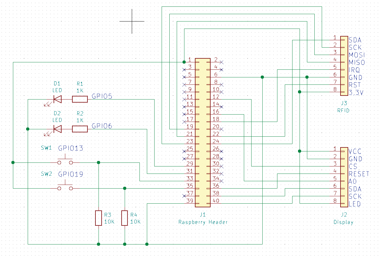
Display and RFID Reader
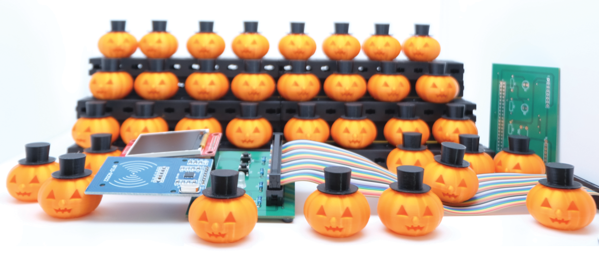
Each of the modules is connected to its own SPI interface. Figure 2 shows the project after the build; the RFID tags are hidden in the pumpkins. Please note that only the Raspberry Pi 4 has multiple on-board SPI interfaces.
The Raspberry Pi 4 has a total of seven SPI interfaces, all of which can be accessed from the 40-pin GPIO header. The previous models came with just three SPI interfaces, of which only two were routed to the header. Table 1 shows which pins correspond to the individual interfaces on the header by default.
|
SPI |
Header |
Pin |
SPI |
Header |
Pin |
|
SPI0 |
MOSI |
19 |
SPI4 |
MOSI |
31 |
|
|
MISO |
21 |
|
MISO |
29 |
|
|
SCLK |
23 |
|
SCLK |
26 |
|
|
CE0 |
24 |
|
CE0 |
7 |
|
|
CE1 |
26 |
|
CE1 |
22 |
|
SPI1 |
MOSI |
38 |
SPI5 |
MOSI |
8 |
|
|
MISO |
35 |
|
MISO |
33 |
|
|
SCLK |
40 |
|
SCLK |
10 |
|
|
CE0 |
12 |
|
CE0 |
32 |
|
|
CE1 |
11 |
|
CE1 |
37 |
|
|
CE2 |
36 |
|
|
|
|
SPI3 |
MOSI |
3 |
SPI6 |
MOSI |
38 |
|
|
MISO |
28 |
|
MISO |
35 |
|
|
SCLK |
5 |
|
SCLK |
40 |
|
|
CE0 |
27 |
|
CE0 |
12 |
|
|
CE1 |
18 |
|
CE1 |
13 |
Reading from the SPI Interface
Notice in Table 1 that some ports overlap and that interface SPI2 is not available on the header in the default configuration. However, the SPI interface configuration can be adjusted with the dtoverlay command, which also lets you output a list of all predefined SPI devices (Listing 1).
Listing 1: SPI Interfaces
$ dtoverlay ‑‑all | grep spi.‑
 spi0‑1cs
 spi0‑2cs
 spi1‑1cs
 spi1‑2cs
 spi1‑3cs
 spi2‑1cs
 spi2‑2cs
 spi2‑3cs
 spi3‑1cs
 spi3‑2cs
 spi4‑1cs
 spi4‑2cs
 spi5‑1cs
 spi5‑2cs
 spi6‑1cs
 spi6‑2cs
The individual interfaces have several configurations, each with a different number of chip select (CS) lines. Therefore, you can configure the interfaces very precisely to suit your project requirements. To get the currently loaded overlays, use the ‑l option. To view the concrete definition of an SPI device, along with the default pins on the header, use the ‑h option (Listing 2).
Listing 2: dtoverlay Output
$ dtoverlay ‑h spi1‑3cs
Name:   spi1‑3cs

Info: Enables spi1 with three chip select (CS) lines and associated
      spidev dev nodes. The gpio pin numbers for the CS lines and
      spidev device node creation are configurable.
      N.B.: spi1 is only accessible on devices with a 40pin header,
      eg: A+, B+, Zero and PI2 B; as well as the Compute Module.

Usage:  dtoverlay=spi1‑3cs,=

Params: cs0_pin       GPIO pin for CS0 (default 18 ‑ BCM SPI1_CE0).
        cs1_pin       GPIO pin for CS1 (default 17 ‑ BCM SPI1_CE1).
        cs2_pin       GPIO pin for CS2 (default 16 ‑ BCM SPI1_CE2).
        cs0_spidev    Set to 'disabled' to stop the creation of a
                      userspace device node /dev/spidev1.0 (default
                      is 'okay' or enabled).
        cs1_spidev    Set to 'disabled' to stop the creation of a
                      userspace device node /dev/spidev1.1 (default
                      is 'okay' or enabled).
        cs2_spidev    Set to 'disabled' to stop the creation of a
                      userspace device node /dev/spidev1.2 (default
                      is 'okay' or enabled).
To output a list of available SPI devices, run:
ls /dev/spi*Make sure you enable SPI support up front with a dtparam=spi=on line in the /boot/config.txt file. Alternatively, you can use the Raspberry Pi OS configuration tool and the 3 Interface Options | I4 SPI option.
If you want to enable certain overlays directly at boot time, you could also add them to the /boot/config.txt file (e.g., dtoverlay=spi1‑2cs). In principle, you could do a software rewire of the individual lines of the SPI interfaces with dtoverlay, but that would be a bit over the top at this point.
Prepping the Pi
The operating system for the Raspberry Pi is an up-to-date 32-bit Raspberry Pi OS Lite. Listing 3 shows the commands for updating the system and installing the required programs and libraries from the package sources. The libraries for integrating the display and reader come from the pip Python Package Index (PyPI).
Listing 3: Preparations
### Update Raspberry Pi
$ sudo apt update
$ sudo apt upgrade
### Install Pi OS packages
$ sudo apt install python3‑pip libopenjp2‑7‑dev libatlas‑base‑dev ttf‑ubuntu‑font‑family
### SPI and graphics libraries
$ sudo python3 ‑m pip install RPi.GPIO spidev Pillow numpy
### Library for the display
$ sudo python3 ‑m pip install st7735
### Library for the RFID reader
$ sudo python3 ‑m pip install pi‑rc522
When you are done, do not forget to enable SPI support for the SPI0 and SPI1 interfaces by opening the /boot/config.txt file in your favorite text editor and adding two lines,
dtparam=spi=on
dtoverlay=spi1‑1cs
to the end of the file. You will need to restart the Raspberry Pi for the changes to take effect.
Setting Up the Display
The sample program Display.py shown in Listing 4 is designed to display the text passed in as a parameter on the display. The system controls the screen with the help of the ST7735 library, which was specially developed to transfer image data to the display.
Listing 4: Display.py
01 from PIL import Image
02 from PIL import ImageDraw
03 from PIL import ImageFont
04 import ST7735
05 import sys
06
07 display = ST7735.ST7735(port=1, cs=0, dc=23, backlight=None, rst=16, width=128, height=160, rotation=0, invert=False, offset_left=0, offset_top=0 )
08 image = Image.new('RGB', (display.width, display.height))
09 draw = ImageDraw.Draw(image)
10 print (len(sys.argv))
11 if len(sys.argv) < 2:
12     print ("Usage: Display.py <TEXT>")
13     sys.exit()
14 draw.text((0, 70), sys.argv[1],  font=ImageFont.truetype("UbuntuMono‑RI",10), fill=(255, 255, 255))
15 display.display(image)
To generate the appropriate image data, access the Pillow image processing library. Pillow (also known as PIL) is a very powerful library with a large number of functions, of which I will only be using a few. The documentation will give you a rough idea of what you can do with Pillow.
When launched, the Display.py script first imports (lines 1 through 5) the ST7735 library, the required parts of Pillow, and the sys library, which lets you read the arguments from the command line. After that, the code creates a display object with parameters suitable for the hardware you are using (line 7).
Line 8 generates an image of a size suitable for the display and stores it in the image object. The commands that follow generate text from the parameter passed in at the command line and insert the text into the image (line 14). The last command then transfers the image to the display.
If you run the program with the
python3 Display.py "Hello world!"command, the Hello world! output immediately pops up on the screen.
Configuring the RFID Reader
The program in Listing 5 reads the individual UIDs from the RFID chips (line 10) and displays them on the screen (line 13). The display is addressed by an external call to avoid the libraries for the display and the reader getting in each other’s way. After outputting the UID, the program reads the first four data blocks from the RFID chip in a loop (starting in line 14) and displays them, too.
Listing 5: RFID Reader
01 import os
02 from pirc522 import RFID
03 rdr = RFID()
04
05 while True:
06   rdr.wait_for_tag()
07   (error, tag_type) = rdr.request()
08   if not error:
09     print("Tag detected")
10     (error, uid) = rdr.anticoll()
11     if not error:
12       print("UID: " + str(uid))
13       os.system('python Display.py "'+str(uid)+' "')
14       for block in [0,4,8,12]:
15         (error,data)=rdr.read(block)
16         print("[ %02d]:"%(block),end="")
17         for c in data:
18           if c<=15:
19             print ("0%x "%(c),end="")
20           else:
21             print ("%x "%(c),end="")
22         print("|",end="")
23         for c in data:
24           if c>65 and c<123:
25             print (chr(c),end="")
26           else:
27             print(" ",end="")
28         print("|")
29 # Calls GPIO cleanup
30 rdr.cleanup()
Note that the reader does not authenticate against the chip, which means that the sample program can only read unprotected chips. If you want to delve a little deeper into the topic of RFID authentication, you can refer to the RC522 library documentation.
I used several smartphone apps to program the chips. NFC Tag Reader is great for getting started and offers numerous functions, although it does have a lot of annoying advertising.
The ad-free team of NFC TagInfo and NFC TagWriter delivers a plethora of information that can be a bit confusing for newcomers; however, breaking the functions down into two apps makes the tools easier to use.
The MIFARE Classic Tool is optimized for working with RFID chips from Mifare and supports authentication. The S50 card included with the reader kit I used in the test, and the RFID tag also included, both support this method.
Conclusions
This article can provide a basis for your own experiments with RFID chips. For many applications, simply reading the tags is enough to get a result. The Pillow library, which I used for the screen output, is also well worth a closer look. Its capabilities go far beyond simply popping up text on a display.