
Automatic Home
With an ESP32 or Raspberry Pi Pico W microcontroller board, you can easily create your own home automation devices. Thanks to ESPHome, you don’t even have to be a programmer.
Many home automation devices can be controlled through WiFi, but often these devices have limitations. For example, they might only work through the manufacturer’s cloud service, they might be difficult to integrate with your own home automation system if you prefer to do everything local, they might lack advanced functionality, or they might be difficult to update.
Luckily, you can install alternative firmware on many existing or homemade devices. In this article, I introduce you to ESPHome, which supports numerous devices with an ESP32, ESP8266, or RP2040 microcontroller (the chip in the popular Raspberry Pi Pico W), although ESPHome support for the RP2040 is still in development. In the examples in this article, I’ll use the Raspberry Pi Pico W. However, if you encounter any issues with your own projects, I recommend an ESP32 development board.
With ESPHome, you can create your own home automation devices with a supported microcontroller board that you connect to LEDs, sensors, or switches. What sets ESPHome apart from other solutions like Arduino or MicroPython is that you don’t need to program. Instead, you configure which components are connected to which pins on the board. ESPHome then generates the necessary C++ code and compiles it into firmware that you can install on the device (see also the “Replacing Firmware on Commercial Devices” box).
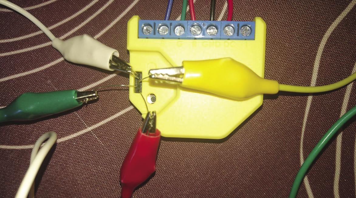
You can replace the existing firmware on commercial devices with ESPHome to gain full control over a device and use it in ways that the manufacturer hasn’t anticipated. Two popular brands that have easy-to-flash devices are Shelly and Sonoff. A website hosts more than 300 ESPHome device configuration templates that can help you get the most out of them. Note that often you’ll need special hardware to flash your own firmware to these devices, at least the first time – afterward you can update them through WiFi. You’ll need a USB-to-TTL adapter and to connect the pins of the adapter to the appropriate GPIO pins on the device. This isn’t always a straightforward process (Figure 1).
Installing ESPHome
ESPHome is a Python program, and most Linux distributions already have Python installed by default. You should first confirm that you have at least version 3.9 installed, by running the command
$ python --version
Python 3.9.15
If your Python version is older, consider upgrading your distribution, or deploy the ESPHome Docker image.
If the Python version looks good, create a virtual environment to contain ESPHome and its dependencies:
$ python -m venv esphome_venv
$ source esphome_venv/bin/activate
Once you’re in the Python virtual environment, install the ESPHome package from PyPI:
$ pip install esphomeAfter the installation is complete, enter
$ esphome version
Version: 2023.6.5
to confirm that ESPHome has been installed successfully.
Creating a Project with the Dashboard
A directory in which you store all of your ESPHome projects is recommended. Suppose you call this directory config. To start the ESPHome dashboard and point it to this directory, run:
$ esphome dashboard config/This command starts a web server on http://0.0.0.0:6052, which you should be able to open in your web browser. If you already have ESPHome devices on your network, the dashboard will automatically discover them.
Next, click New Device at the bottom right corner, and then Continue. Give your device a name and enter the SSID and password for the WiFi network to which you want your device to connect, then click Next and select your device type (Figure 2).
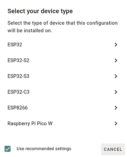
In this example, choose Raspberry Pi Pico W; for an ESP32 or ESP8266 you also need to select the specific board. The dashboard then creates a minimal configuration and shows an encryption key that you can use to allow the ESPHome device to communicate with Home Assistant, a popular open source home automation gateway developed by the same team behind ESPHome. Finally, click Install.
You can use several methods to install ESPHome to your device, but not all of them are supported by every device. Because no ESPHome firmware is running on the device yet, the first method (over WiFi) is not possible; the Plug into the computer running ESPHome Dashboard choice isn’t available either. You can always choose Manual download, which has instructions on how to accomplish the installation (Figure 3).
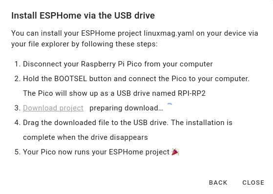
For the Raspberry Pi Pico W, you’ll need to disconnect the board from USB, hold the BOOTSEL button while reconnecting the board, and then release the button, which causes a USB drive named RPI-RP2 to appear in your file manager. Now, click Download project and drag the .uf2 file to the USB drive. Once the drive disappears, the board runs your ESPHome firmware, and you can click Close.
Default ESPHome Configuration
In the ESPHome dashboard, click Edit in the box representing your device to open your device configuration in a web editor. The configuration file is written in YAML, with various key-value pairs for different options (Listing 1).
Listing 1: Pi Pico W Default Config
esphome:
  name: linuxmag
  friendly_name: linuxmag

rp2040:
  board: rpipicow
  framework:
    # Required until https://github.com/platformio/platform‑raspberrypi/pull/36 is merged
    platform_version: https://github.com/maxgerhardt/platform‑raspberrypi.git

# Enable logging
logger:

# Enable Home Assistant API
api:
  encryption:
    key: "7wFO19sSMAkGX008l+wX4u53hBz/a1Ha+9bAdouUjo8="

ota:
  password: "20e3778465f1c5b147f8645dc237b146"

wifi:
  ssid: !secret wifi_ssid
  password: !secret wifi_password

  # Enable fallback hotspot in case wifi connection fails
  ap:
    ssid: "Linuxmag Fallback Hotspot"
    password: "DVaDAPFJN5cA"
As you can see, this configuration file sets the device name and its friendly name, as well as the platform and board. It then enables logging and the Home Assistant API, sets a password for over-the-air (OTA) updates, and configures WiFi credentials and a fallback hotspot in case the WiFi connection fails. If a failure happens, you can connect with your mobile phone to the hotspot of the device to reconfigure the network. The WiFi credentials are stored in a separate file, secrets.yaml, which prevents accidental exposure of sensitive information when sharing your device configuration with others.
Note that if you don’t use Home Assistant, you should remove the api line and the two lines that follow; otherwise, your ESPHome device keeps waiting for a connection from Home Assistant. If no connection is established within 15 minutes, the device will assume that something’s wrong and reboot.
Blinking the Built-In LED
Now you can modify this configuration in the web editor or in your favourite desktop or command-line editor. The configuration file is saved in the config directory you created. In the next exercise, make the board’s built-in LED blink by adding the configuration shown in Listing 2.
Listing 2: Blinking LED
output:
  ‑ platform: gpio
    pin:
      number: 32
      mode: output
    id: LED

interval:
  ‑ interval: 1000ms
    then:
      ‑ output.turn_on: LED
      ‑ delay: 500ms
      ‑ output.turn_off: LED
Make sure to use the correct indentation because spaces are important in YAML. This configuration adds an output component from the gpio platform on pin 32, which corresponds to the built-in LED on the Raspberry Pi Pico W. Additionally, an interval component is defined that is triggered every 1000ms. On each trigger, it turns on the output with id: LED, waits 500ms, and then turns off the same output.
After saving the file (in the web editor at the top right), click Install in the dropdown menu of the node and choose your installation method. This time you can choose Wirelessly, because your device is already running ESPHome and is connected to your WiFi network. Your device doesn’t even need to be connected to your computer’s USB port any more. Your YAML configuration is now transformed into C++ code and compiled. If you see the message INFO Successfully compiled program, the dashboard will upload the new firmware. Once your device reboots, the LED starts blinking.
Adding Your Device to Home Assistant
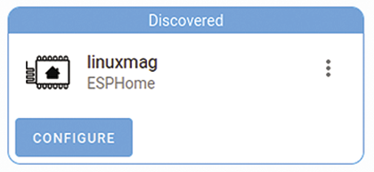
If you’re running Home Assistant on your home network, your ESPHome device will be recognized automatically. In your Home Assistant dashboard, click Notifications in the sidebar and then Check it out at the New devices discovered message. You will see the name you assigned to your ESPHome device (Figure 4). Click the Configure button and then Submit to add the ESPHome device to Home Assistant.
You will be asked to enter the device’s encryption key. Go to the ESPHome dashboard and find the key in the device’s YAML code. Alternatively, click on the three dots in the box representing your device, then Show API Key. Next, click Copy and paste the key in the Encryption key field of Home Assistant. After clicking Submit, optionally choosing an area, click Finish to complete the process. The device is added to Home Assistant.
Remotely Control the LED
Now that you have configured your device to blink its LED and added it to Home Assistant, you might want to control it remotely. Instead of having the LED blink automatically, modify the configuration to allow you to control the LED from Home Assistant’s dashboard. The required changes are simple: In the YAML configuration file, remove the entire interval block, change the output key to switch, and change the id key to name. You can find the modified configuration (without the defaults that you leave unchanged) in Listing 3.
Listing 3: Remote LED Control
switch:
‑ platform: gpio
pin:
number: 32
mode: output
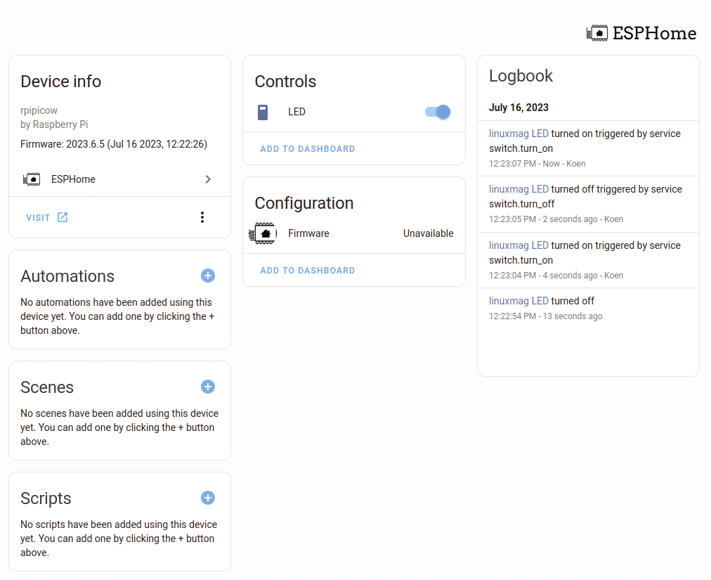
name: LEDAfter installing the firmware on your device, you can control the built-in LED from Home Assistant’s dashboard (Figure 5). Because you have defined the LED as a switch component, you can turn it on and off.
Adding Sensors
Controlling a simple LED is relatively easy with alternatives like an Arduino sketch or some MicroPython code. However, things become more complex when you start connecting sensors. This is where ESPHome shines. The ESPHome website provides documentation for various supported sensors, each with simple YAML examples.
Take the MH-Z19 CO2 sensor, for example. This sensor is useful to have at home, especially considering the importance of ventilation in the fight against viruses. The worse the ventilation in a home, the higher the concentration of CO2. Not only is CO2 concentration – [CO2] – a good indication of the need for ventilation, it has various health hazards on its own.
Connecting the CO2 Sensor
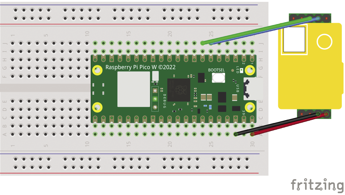
The ESPHome documentation provides instructions on how to connect and configure the MH-Z19 sensor. First, you disconnect your Raspberry Pi Pico W from power and put it on a breadboard. You will be using four pins on the MH-Z19: VIN, GND, RX, and TX. Their names are listed on the bottom of the sensor board. Additionally, consult the Raspberry Pi Pico W pinout or the pinout of the other microcontroller board you’re using.
Connect the VIN pin of the sensor to the VBUS (which receives 5V from the USB power supply) of the Raspberry Pi Pico W, GND to GND, RX to GP4, and TX to GP5 (Figure 6). The configuration for the sensor is shown in Listing 4.
Listing 4: CO2 Sensor over UART
uart:
  rx_pin: 5
  tx_pin: 4
  baud_rate: 9600

sensor:
  ‑ platform: mhz19
    co2:
      name: "MH‑Z19 CO2"
    temperature:
      name: "MH‑Z19 Temperature"
    update_interval: 60s
In this configuration, you define a UART bus on pins GP4 and GP5, operating at 9600 baud. Note that the RX defined here is connected to the TX of the sensor, and vice versa. The configuration also defines the CO2 sensor, which measures both [CO2] and temperature and sets the update interval to once per minute. You can remove the switch for the LED from the configuration because you don’t need it here.
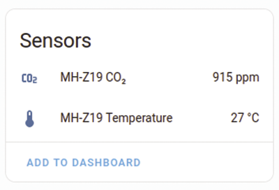
After installing this configuration, you’ll see the current CO2 concentration in parts per million (ppm) appearing in Home Assistant and in the logs on the ESPHome dashboard. Be sure to read the ESPHome documentation on calibrating the sensor to ensure accurate measurements. Note that the internal temperature sensor of the MH-Z19B isn’t that accurate; it’s primarily used as a reference for the CO2 sensor.
Automated CO2 Alarm
You can now read the CO2 values in your Home Assistant dashboard (Figure 7), but you might not always be looking at your computer or phone screen. Fortunately, we already know how to control the built-in LED. In principle you can now add an automation in Home Assistant that turns on the LED on your Raspberry Pi Pico W when the CO2 level is too high. However, this detour is not necessary; you can achieve the same result with ESPHome’s built-in automation features. The advantage is that these automations continue to work even when your Home Assistant installation or MQTT broker (see the “MQTT Broker” box) is offline or your network connection is down.
If you don’t use Home Assistant – or if you prefer not to use the Home Assistant API – ESPHome also supports communication through the MQTT machine-to-machine messaging protocol. This route requires you to set up an MQTT broker, such as Eclipse Mosquitto, running in a Docker container or as a Home Assistant add-on. Then you add an MQTT Client Component to your ESPHome device configuration, specifying which MQTT broker to connect to, as well as the username and password for authentication. At this point, you can control the switches defined in your device by sending MQTT messages to your broker, and you can subscribe to MQTT messages from the sensors defined in your device.
To make your Raspberry Pi Pico W board act as a CO2 alarm, turn on the built-in LED when the CO2 concentration exceeds 1,000ppm (Listing 5).
Listing 5: CO2 Sensor with LED Alarm
output:
  ‑ platform: gpio
    pin: 32
    id: co2_alarm

uart:
  rx_pin: 5
  tx_pin: 4
  baud_rate: 9600

sensor:
  ‑ platform: mhz19
    co2:
      name: "MH‑Z19 CO2"
      id: co2_value
      on_value_range:
        ‑ above: 1000
          then:
            ‑ output.turn_on: co2_alarm
        ‑ below: 1000
          then:
            ‑ output.turn_off: co2_alarm
    temperature:
      name: "MH‑Z19 Temperature"
    update_interval: 60s
This code first defines the LED as an output, rather than a switch, so it’s not controllable through Home Assistant or MQTT. The id lets you refer to the LED in the configuration of the CO2 sensor.
Next, it modifies the co2 section in the CO2 sensor configuration, which configures the sensor to turn on the LED with ID co2_alarm when the CO2 value exceeds 1,000ppm and turns it off when the CO2 value drops below 1,000ppm. Your CO2 alarm will now function even without a network connection. When you see the built-in LED turn on, you’ll know that it is time to open the windows for ventilation.
Adding a Display
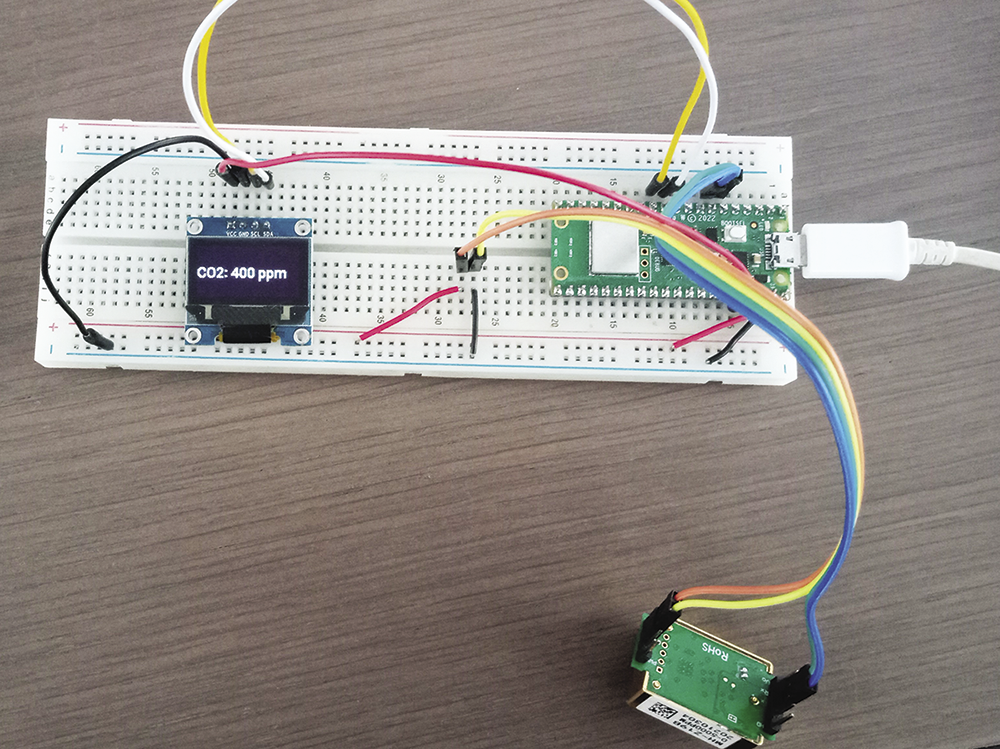
If you want more than just an LED on your device and prefer to see the full sensor value, you can add a display. ESPHome supports various display components, and this example uses an SSD1306. Start by disconnecting power from your Raspberry Pi Pico W and then connecting the display to your breadboard. Connect it as follows: the VCC of the display to 3V3 Out of the Pico W, GND to GND, SDA to GP8, and SCL to GP9 (Figure 8). Listing 6 shows the code you need to add to Listing 5 to show the sensor values on the display.
Listing 6: Display Showing [CO2]
i2c:
  sda: 8
  scl: 9

font:
  ‑ file: "gfonts://Roboto@medium"
    id: font_roboto
    size: 18

display:
  ‑ platform: ssd1306_i2c
    model: "SSD1306 128x64"
    address: 0x3C
    lambda: |‑
      it.printf(0, 23, id(font_roboto), "CO2: %.0f ppm", id(co2_value).state);
The SSD1306 display uses the I2C bus (there’s also an SPI version), so first define this bus in the ESPHome configuration. If you use other pin numbers on the Raspberry Pi Pico W, make sure to use pins that are designated I2C0 in the pinout, because I2C1 isn’t supported yet by ESPHome.
Because you want to show letters and numbers on the display, you also need to define a font. This example uses Roboto font size 18. The display is now defined and uses the previously defined I2C bus, specifying the model and I2C address of the display. The last line is the first real code in this article. This lambda is C++ code integrated in your ESPHome configuration. Although most ESPHome configurations can be defined without programming, displays are one of the few components that require code.
In this example, the one-liner calls the printf method on the display, specifying the horizontal and vertical coordinates in which to place the text, the id of the font, the string template to display, and the state you want to display. The value is obtained by referring to the ID of the CO2 sensor and getting its state property:
id(co2_value).stateBecause this is a floating-point number (e.g., 1746.00), the %.0f pattern shows only the integer part (i.e., 1746).
Complex Devices
The full YAML file of this CO2 sensor device isn’t very long, but you can create much more complex configurations. For example, I created an ESPHome air quality monitor that combines a CO2 sensor with a particulate matter (PM) sensor, temperature-humidity-pressure sensor, and display. I’ve also created an ESPHome configuration for the M5Stack PM2.5 air quality kit, as well as an ESPHome heart rate display showing heart rate from a Bluetooth Low Energy (BLE) heart rate sensor on a display.
Finally, if you want to learn more about ESPHome and explore various examples to create your own home automation devices, read my book on the topic.