
Flying High
A Raspberry Pi running Linux with a custom I2C card and a small power supply provides an interface for a real-time flight simulator.
In a flight simulation, the equations must be solved at a sufficiently fast rate that the motion (or dynamics) of the simulated aircraft appears to be smooth and continuous, with no delays or abrupt changes resulting from the computations (Allerton, D. J. Principles of Flight Simulation. John Wiley and Sons, 2009). Typically, the real-time software in a flight simulator updates at least 50 times per second. In other words, all the computations must be completed within 20ms, including the inputs from controls, levers, knobs, selectors, and switches, which must be sampled within the 20ms frame.
Data acquisition of analog and digital inputs is potentially slow. In the case of analog inputs, the signals are sampled, converted, and read into a computer as digital values, and a flight simulator might have several hundred inputs. To illustrate the problem, in a flight simulator that acquires data from 32 analog inputs at 50Hz, the overall sampling rate is 1,600 samples per second. Furthermore, the data must be sampled with sufficient resolution (or accuracy), typically 12-16 bits, and any latency resulting from data acquisition by the simulator modules must be minimized. To avoid any delays caused by simulator modules waiting to capture data, a dedicated I/O system can acquire the data and transfer it to the simulator modules over a local network.
Requirements
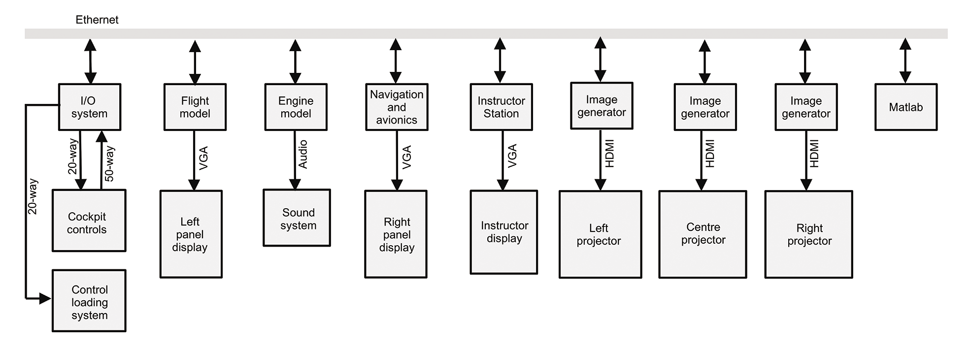
A real-time research flight simulator (Allerton, D. J. Flight Simulation Software: Design, Development and Testing. John Wiley and Sons, 2023) currently installed at Cranfield University (Cranfield, UK), runs on a local network of eight PCs, with the simulation functions partitioned as shown in Figure 1. The I/O system provides an interface between the simulator and the software modules that comprise: the modeling of the aircraft aerodynamics and the engine dynamics, aircraft systems, flight displays, navigation, avionics, an instructor station, control loading, sound generation, flight data recording, three image generators for a visual system, and an optional connection to Matlab. Data is transmitted over the network as broadcast Ethernet UDP packets.
Previously, the I/O system was based on a PC with a set of industrial I/O cards to acquire digital and analog inputs and generate digital and analog outputs. However, the interface cards and the PC used in this I/O system were obsolete, and the Raspberry Pi (RPi) offered a potential replacement. The RPi has sufficient performance to compute the I/O functions in real time, and much of the existing C code could be reused to run under the RPi’s Linux operating system. The RPi Ethernet port provides UDP connection to the simulator computers.
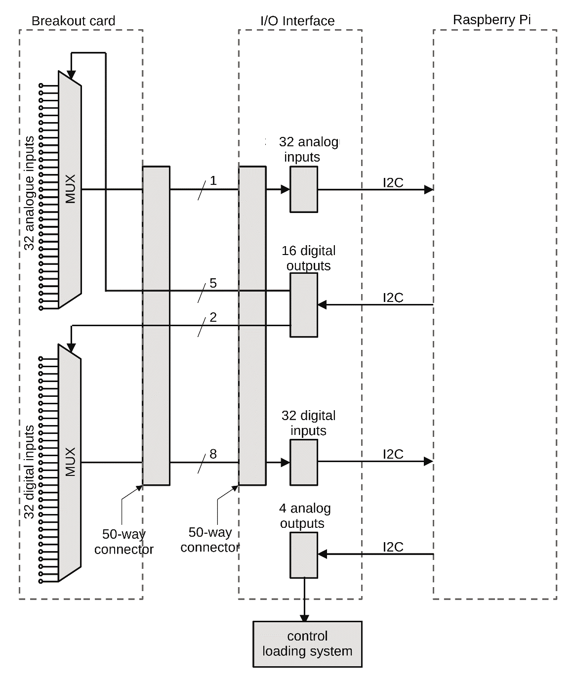
The overall structure of the I/O system is shown in Figure 2. The simulator outputs are connected to an existing breakout card, which provides interconnections to the simulator and signal conditioning. The analog multiplexer selects one of 32 inputs, where the channel number (0-31) is given by a 5-bit input. The digital multiplexer selects one of four groups of 8 bits, where the channel number (0-3) is given by a 2-bit input. The selected analog channel is sampled by an analog-to-digital (A/D) chip, and the digital inputs are read into an 8-bit parallel buffer. The four analog outputs drive an electrical control loading system, which provides an artificial feel for the control column and rudder pedals. The breakout card and the I/O interface are connected by a 50-way ribbon cable.
The primary requirement was to provide an I/O interface compatible with the RPi, capable of sampling 32 analog inputs and 32 digital inputs at 50Hz and generating four analog outputs and 24 digital outputs, also at 50Hz, where the resolution of the A/D conversion for the flight simulator is 12 bits. Because no commercial I/O cards for the RPi met this specification in terms of the number of channels, resolution, and sampling rate, a custom solution was developed.
I2C
The 40 GPIO lines of the RPi include support for I2C transfers. The I2C protocol, originally developed by Philips, is an interesting approach to interfacing, requiring only two lines to transfer data between devices connected to an I2C bus: a serial data line (SDA) and a serial clock line (SCL). For the RPi, SDA and SCL are included in the GPIO pinout. I2C chip pinouts provide SDA and SCL, a reference voltage, ground, and control pins. Additionally, some I2C chips include pins to define the device address. The I2C protocol offers two advantages: First, the connection to an RPi only requires a few lines; second, a wide range of integrated circuits (ICs) is available for the majority of I/O functions, typically costing less than $10.
One further attraction of an I2C interface is the simplicity of programming. Most transfers only require output of the device address to select a specific register of a chip and then transfer of data to or from an external device. I2C chips are compliant with the I2C data transfer protocol, so a designer only needs to ensure that the RPi activates the SDA and SCL pins in accordance with the protocol, which is provided in software by an I2C driver.
Several I2C libraries are available for the main programming languages, including i2c-tools and wiringpi, simplifying the development of application software for I2C devices. The i2c-dev library is integrated with libc for the RPi and, for programming in C, includes the appropriate header files i2c.h and i2c-dev.h.
A number of manufacturers support I2C for analog and digital data transfers. The Microchip Technology family of devices was selected for the I/O system because it met the requirements and the cost constraints and operates within the 0-5V range of the simulator equipment. The MCP23008 parallel I/O expansion IC is an 18-pin chip, with eight data lines that can be set individually as inputs or outputs. The MCP3221 IC provides 12-bit A/D conversion with a sampling rate in excess of 20,000 samples per second. The MCP4728 IC provides four 12-bit digital-to-analog outputs, with a conversion time of less than 6µs. The base addresses of these devices are factory set but can be modified by selection of the address lines or by reprogramming the address (not recommended for the faint-hearted). Surface-mount variants were selected for the interface printed circuit board (PCB), although many I2C chips are also available as dual in-line (DIL) packages.
The interface also includes connectors to the breakout card and a voltage level translator to connect the RPi with external inputs and outputs operating at 5V. A Texas Instruments PCA9306 converts SDA and SCL signals between the different voltage levels; the Microchip Technology components are connected to external devices requiring a 5V reference, whereas the RPi operates with a 3.3V reference.
System Design
The requirement of the I/O system was to provide five functions:
- Controlling two multiplexers of the breakout card
- Reading the 32 multiplexed digital inputs
- Reading the 32 multiplexed analog inputs
- Driving four analog outputs (control loading system)
- Providing digital outputs for the multiplexers, the simulator lamps, and an LED diagnostics panel
One MCP23008 is configured for eight outputs to drive the two multiplexers, and a second MCP23008 is configured for eight inputs to read the digital inputs. The MCP3221 has one analog input in the range 0-5V, and the MCP4728 provides four analog outputs in the range 0-5V. The pin connections of these three integrated circuits are shown in Figure 3.
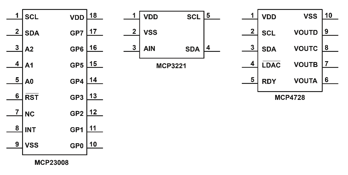
The 5V supply reference VDD, the 0V ground reference VSS, and the I2C signals SCL and SDA are common to all three ICs. For the MCP23008, the address lines A0, A1, and A2 can be pulled up to VDD or grounded to select up to eight addresses. The data lines GP0-GP7 provide 8-bit input or output. The reset line ¬RST is pulled up to VDD and the interrupt line INT is not used. For the MCP3221, the single-ended analog input is connected to pin 3. For the MCP4728, the four analog outputs are available at pins 6-9. The ready RDY line is not used and the output latching pin ¬LDAC line is grounded.
In effect, the board reduces to seven ICs, plus two support ICs, with five MCP23008 ICs for digital input, digital output, and multiplexer control (40 bits); an MCP3221 for analog input; and an MCP4728 for analog output. One of the MCP23008 ICs drives eight outputs for an LED display, an LM7805 voltage regulator provides a stable 5V reference for the A/D chip and a PCA9306 voltage level translator converts I2C signals between the RPi (3.3V) and the Microchip Technology ICs (5V). An additional I2C temperature sensor was included on the board.
Software
For the RPi model 3, the I2C driver is enabled by running raspi-config and selecting the I2C configuration setting (400KHz baud rate). With the I2C board connected, the terminal command
i2cdetect -y -1identifies the I2C devices and their specific addresses. The relevant I2C header files must be included, and the I2C addresses of the devices are defined, in the program to improve readability:
#include <linux/i2c.h>
#include </i2c-dev.h>

#define DIGITAL_OUTPUT1_ADR 0x20
#define DIGITAL_OUTPUT2_ADR 0x21
#define DIGITAL_INPUT_ADDR 0x22
#define MUX_ADR 0x23
#define LEDS_ADR 0x24
#define ADC_ADR 0x4d
#define DAC_ADR 0x60
Before accessing the I2C devices, it is essential to check that they are addressable with a simple test:
i2c = open("/dev/i2c-1", O_RDWR); /* check I2C device is available */
if (i2c < 0)
I2Cerror("unable to access I2C bus\n");
if (ioctl(i2c, I2C_SLAVE, ADC_ADR) < 0) /* check A/D is accessible */
I2Cerror("unable to access ADC (%2x)\n", ADC_ADR);
The open function checks that access to the I2C devices is enabled. The ioctl call checks specific devices, in this case the A/D chip with an address ADC_ADR; this ioctl call is repeated for all the devices in use.
Two C structures are defined to access the I2C devices, where the fields of the structures are defined in the header file i2c-dev.h:
struct i2c_rdwr_ioctl_data packets;
struct i2c_msg          messages[1];
Because the MCP23008 8-bit bidirectional buffers are dedicated to input or output, the direction can be set on initialization. For example, the multiplexer (MUX) is set as an output in Listing 1.
Listing 1: Setting MUX
01 buf[0] = 0;
02 buf[1] = 0;  /* set for 8 outputs */
03
04 messages[0].addr  = MUX_ADR;
05 messages[0].flags = 0;
06 messages[0].len   = 2;
07 messages[0].buf   = buf;
08 packets.msgs      = messages;
09 packets.nmsgs     = 1;
10 if (ioctl(i2c, I2C_RDWR, &packets) < 0)
11     I2Cerror("unable to set the MUX dir reg\n");
Similar code is used to set the other 8-bit buffers for input or output. As an example, sampling the 32 analog input channels is illustrated by the code in Listing 2. The multiplexer is set to the channel value chn, and the A/D chip value is read as 2 bytes to the array inbuf. The result is formed by combining the most significant four bits in inbuf[0] with the least significant 8 bits in inbuf[1], which is stored in array AnalogueData[] of 32-bit unsigned integers. With the I2C configured for a baud rate of 400Kbits/s, an RPi 3 Model B samples 32 analog inputs in 8.4ms, which is less than half the 20ms frame time.
Listing 2: Sampling Analog Input Channels
01 for (chn=0; chn<=31; chn+=1)
02 {
03     outbuf[0]         = 9;  /* reg 9 channel number for analogue mux */
04     outbuf[1]         = (unsigned char) chn;
05
06     messages[0].addr  = MUX_ADR;
07     messages[0].flags = 0;
08     messages[0].len   = 2;
09     messages[0].buf   = outbuf;
10     packets.msgs      = messages;
11     packets.nmsgs     = 1;
12     if (ioctl(i2c, I2C_RDWR, &packets) < 0)
13         I2Cerror("unable to set the analogue MUX dir reg");
14
15     messages[0].addr  = ADC_ADR;
16     messages[0].flags = I2C_M_RD;
17     messages[0].len   = 2;
18     messages[0].buf   = inbuf;
19     packets.msgs      = messages;
20     packets.nmsgs     = 1;
21     if (ioctl(i2c, I2C_RDWR, &packets) < 0)
22         I2Cerror("unable to read ADC ch=%d\n", chn);
23
24     AnalogueData[chn] = (((unsigned int) inbuf[0] & 0xf) << 8) + (unsigned int) inbuf[1];
25 }
For the flight simulator, after initialization, the I/O system repeatedly executes a loop that comprises broadcasting a UDP packet containing the sampled data, reading 32 analog inputs, reading 32 digital inputs, writing four analog outputs, writing four digital outputs, responding to UDP packets from the simulator PCs, and updating a small LED display. The interface is scalable and includes expansion for additional digital inputs and outputs. Additionally, the RPi interface provides a timing reference for the simulator, ensuring accurate maintenance of the frame rate.
Board Design
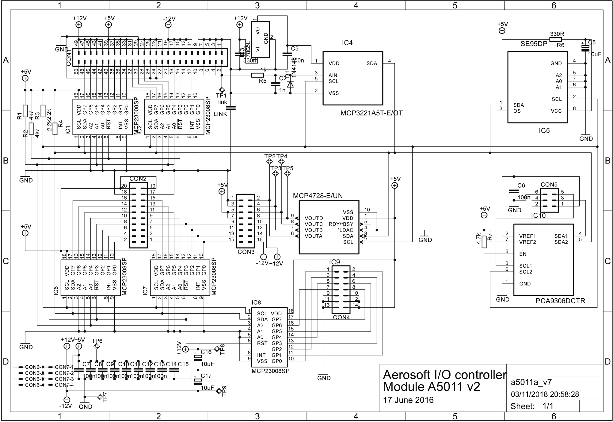
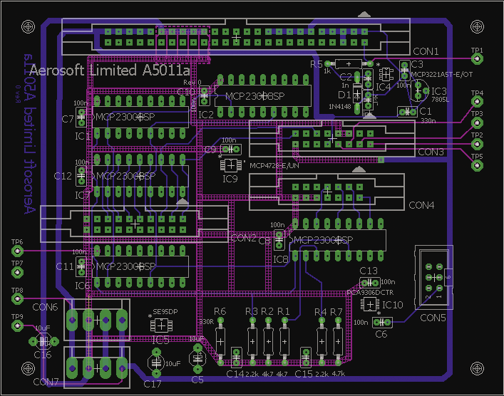
The schematic is shown in Figure 4. The PCB was produced as a four-layer board (120mmx95mm) by Eagle CAD software (Figure 5). The design illustrates the simplicity of I2C interfacing for the data acquisition application.
Observations
I2C is a mature and stable protocol supported by a wide range of integrated circuits in both DIL and surface-mount formats, mostly costing less than $10. The RPi provides an interface for I2C devices, requiring only two lines plus power and ground so that construction of an interface with breadboard, wire-wrap, or PCB is straightforward. For the flight simulator application, I2C fully meets the requirements in terms of sampling rates, resolution, and data throughput. With the GNU GCC tool chain, programming of the I2C devices was straightforward and required only a few lines of code to access each device.
The RPi provides a dedicated headless I/O system, loading and running automatically after power-up and with diagnostic information on the system status provided by a small LED panel. The interface provides raw I/O data for the simulator modules, enabling any scaling or conversion to be applied in the modules.
A Raspberry Pi running under Linux with an I2C interface and a small power supply replaced a PC with two large industrial I/O boards, reducing both the footprint and the cost of the I/O system for a real-time flight simulator. Much of the existing I/O software was reused, and no changes were required to the simulator software.