Greenhouse Control
You can safely assign some greenhouse tasks to a Raspberry Pi Pico W, such as controlling ventilation, automating a heater, and opening and closing windows.
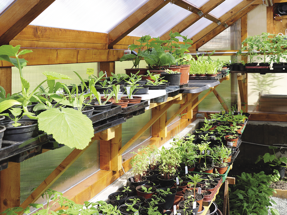
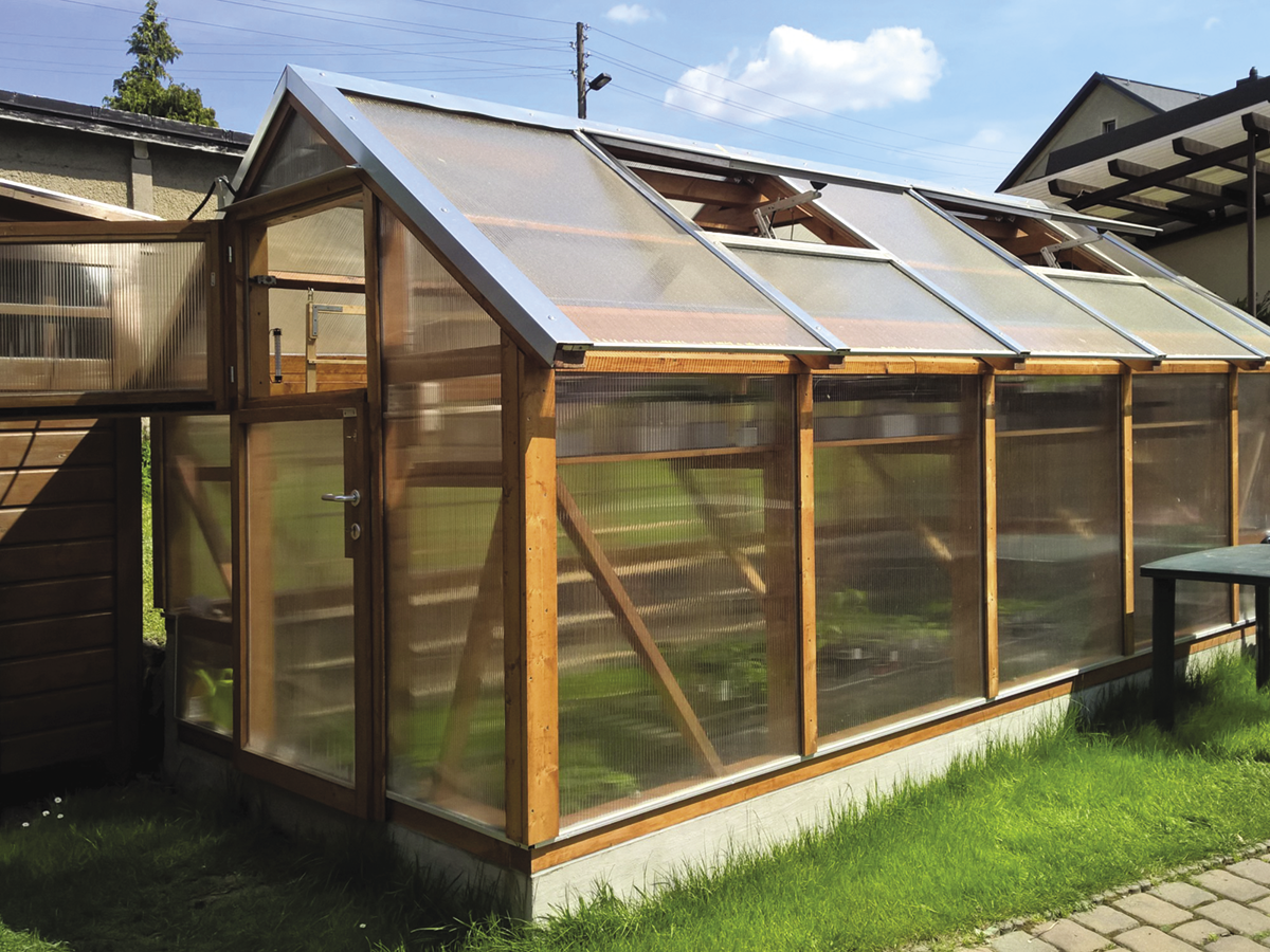
When implementing my greenhouse control system, I didn’t have to start completely from scratch. An older control system already existed with which I had a little experience. Building on this established setup, I decided to use power windows for the hinged skylights (Figure 1) and a fan to circulate the air in the greenhouse. Also, when nighttime temperatures dropped in the spring and fall, I wanted a heater to switch on automatically. In contrast, crops needed protection against excessive heat in summer.
An intelligent control system would also be nice to reference the outside temperature, allowing it to close the windows in time for cool evenings and build up a heat reserve for young crops during the night. At the same time, a reliable clock was essential to adapt to the lighting conditions of different seasons.
All functions should be remotely accessible, with the option to intervene over the web if thresholds were exceeded. Another requirement was an activity log to collect messages from ongoing operations for remote viewing without always having to check the display in the greenhouse. To implement all of this, I used a Raspberry Pi Pico W. In addition to the essential peripheral devices, it now provides the entire logic and a web server.
Getting Started
Unlike the single-board computers from the Raspberry Pi family, the Pico requires very little preparation. I used the WiFi version because the controller could not be managed remotely without a connection to the home WiFi network. I also needed a USB port for the programming. In the development phase, you need to feed the commands externally from the special Python Thonny integrated development environment (IDE) to the controller, and to finish the job, you need to transfer your code to the module permanently.
One advantage of microcontrollers over computers with filesystems is their robustness, with no risk of the SD card or hard drive being damaged by a power failure. You do not need to shut down your controller in a defined way beforehand when switching it off and can instead simply press the power switch. In return, you have to make do with fewer resources and without a battery-buffered real-time clock in the case of the Pico. Luckily, this restriction did not matter for my control system, because I designed in a real-time clock (RTC) to exchange information with a time server on the Internet. The project also had electrically erasable programmable read-only memory (EEPROM) to store the latest setting values.
Setup
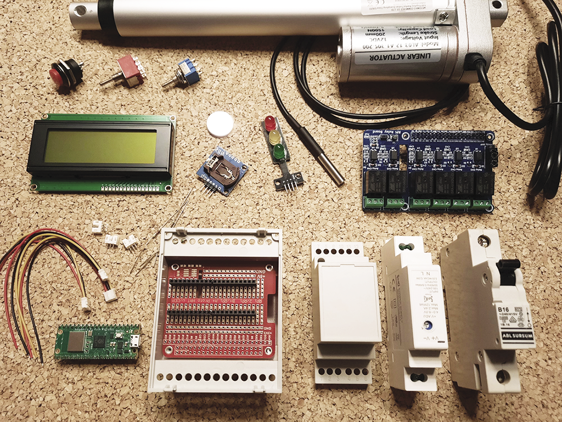
The LCD display and the RTC are connected to Pico over an I2C bus and the temperature sensors over a 1-Wire bus. The transistors are connected upstream of the LEDs that occupy three ports. To allow the Pico to control the large consumers such as the window lifters and heater (230V), a relay board with six inputs was also controlled by the Raspberry Pi GPIOs. In this use case, the Pico sits in a housing and on its own small circuit board. All other components (see the “Parts List” box) were connected by plug connectors and put in a DIN top-hat rail housing (Figure 2). The idea was to keep things manageable for any service work and to be able to disconnect all the components easily.
• Raspberry Pi Pico W
• LCD panel with I2C controller
• DS1307 real-time clock with AT24C32N EEPROM
• DS18B20 temperature sensor
• 12V electric window lifters (2)
• 6x relay board
• LED board
• Transistors, resistors
• 5V and 12V supply (for top-hat rail)
• Automatic circuit breaker (for top-hat rail)
• Various empty housings (for DIN rail)
• Housing (fuse box)
• Wiring, installation material
A 5V power supply powers the entire circuitry, and 12V is required for the window motors. In case of activity, the current there needs to be relatively high. To avoid the power supply being constantly idle, and to remove the need for DC/DC converters, the 12V motor power supply is only switched on with a relay when needed. Most of the time, I make do with a frugal 5V circuit to save money.
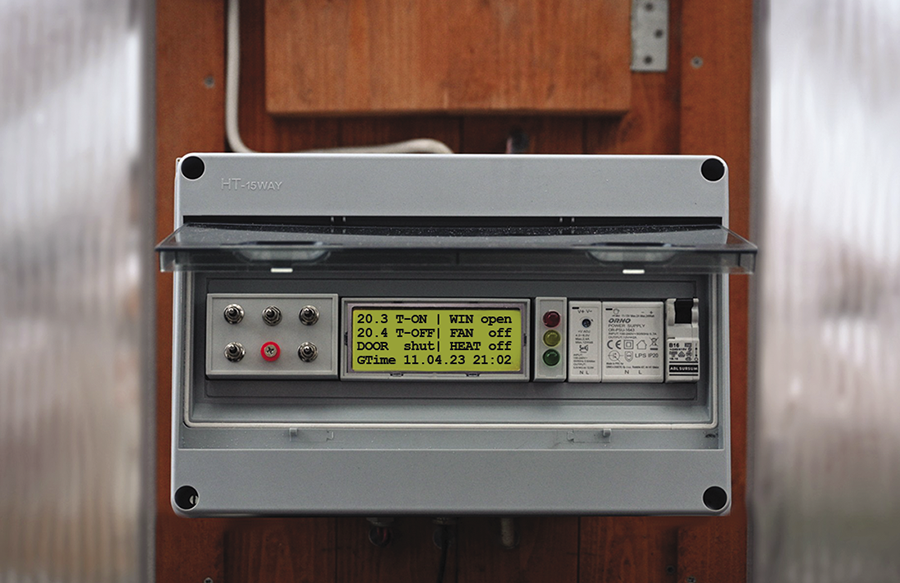
Most of the hardware is housed in a prefabricated enclosure – a fuse box with a weatherproof seal (Figure 3). I wanted to take advantage of a DIN top-hat rail housing to be able to arrange and exchange individual modules easily side by side. Whatever didn’t fit beside the circuit breaker and power supply units was located in empty housings for the top-hat rail (e.g., LCD display, switches, and LED). Enough space was left in their housings to install the Pi, the relay board, and the rest of the electronics closer to the rear, resulting in an uncluttered front side.
I then routed the wires out to the lift motors, fan, heater, door contact, temperature sensors, and network connection through the enclosure, making sure that everything was watertight. All of the outdoor wires first were routed to clamp connectors on the inside so the control and switch enclosure could be tested separately from the rest of the external installation and be easily assembled.
Control
If you take a look at the few alternatives available for purchase, you’ll quickly discover that various controllers are often limited to thermostats only and are difficult to expand. However, I wanted to use my own accessories and be able to program everything. To operate the solution, I use a central control script main.py in the usual style for the Pico and added methods for the LCD controller and DS1307 chip to the source code.
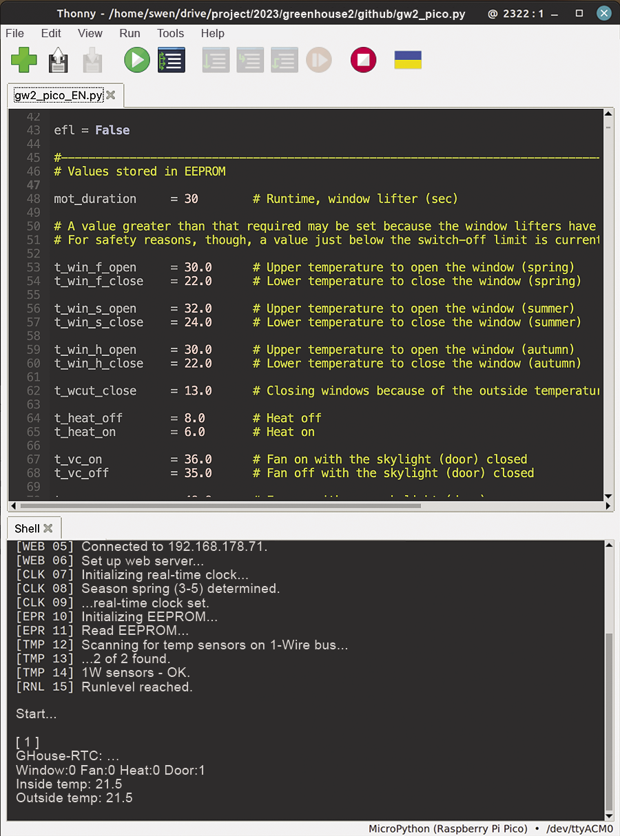
Development occurred in the Python Thonny IDE (Figure 4), which integrates the Pico seamlessly. MicroPython was the programming language of choice. If you have a device without MicroPython, you first need to take care of loading the latest firmware. Numerous workable how-tos for this step can be found on the Internet.
After applying the operating voltage, the Raspberry Pi initially checks to see whether all of the components are in place and whether all of the peripherals can be accessed by I2C or the 1-Wire bus. If this is the case, the system can be fired up. In the case of less serious events, such as a missing Internet connection or an inaccessible time server, the system continues and tries to establish contact at a later time. After that, the Pico lowers the windows to the stop position to adjust the zero points in case the windows were open. The window lifters have internal stop switches, so I didn’t have to connect anything to the Pi.
The current operating values are queried in an infinite loop and checked for the designated upper and lower limits for switching the actuators, followed by appropriate actions. The system is really smart in this way because a variety of indoor and outdoor conditions play a role. For example, knowing whether the access door is open or closed is important for ventilation, and different switching values for everything depend on the time of year because climate parameters such as insolation will vary. The controller also provides different hystereses depending on the time of day, to avoid repeated switching. In the evening, for example, the windows are kept closed longer to store some heat for the night.
The script is also responsible for displaying the current values on the LCD display of the control panel on the outer wall and for writing logs, which you view in the web app. Scheduled actions are reported in the message log, as well as exceptions into a separate error log, such as a sensor failure or exceeding maximum or minimum temperature limits, because errors and warnings are retained for a longer period of time. At the end of the day, then, you can find out what has been going on with a quick check of the app or the LCD display.
The corresponding switching values are defined as constants in the source code by default. If required, the constants can be customized later in the EEPROM, which you can also write to from the web app. For the app to work at all, the script keeps trying to reconnect at regular intervals after a connection loss. The exact time is also resynchronized regularly. In general, the Raspberry Pi’s MicroPython interpreter should never stop, if possible; you want it to keep things under control whatever else happens.
I worked with the uasyncio library to allow ongoing operations and web interface updates to take place in parallel. The library provides an asynchronous scheduler that assigns application time to both tasks, which makes it a great choice for this use case: to ensure smooth operations (short response time after pressing a button in the web interface) on the one hand and smooth processing of the program (avoiding long waits for requests from the web server) on the other.
Of course, you also want to be able to control all of the functions manually as an alternative. For this to happen, a multipole switch disconnects the actuators from the control system so that each of the two windows can then be set to the desired position without conflicting with the automatic system, and the fan and heater can be set. The LCD display backlighting also is manually switched on to make it easier to read in the evenings.
Web-Based Remote Control
The control system works reliably offline, but in my opinion, remote web-app-based access (Figure 5) is a great idea because it avoids the need to check everything manually onsite. Also, it means you do not have to make the control panel on the greenhouse too fancy. In support, the Pico can run a web server, which then gives you a user interface (Figure 5). If so desired, you can additionally share the interface on the Internet, but in this case, it can only be accessed on the local network.
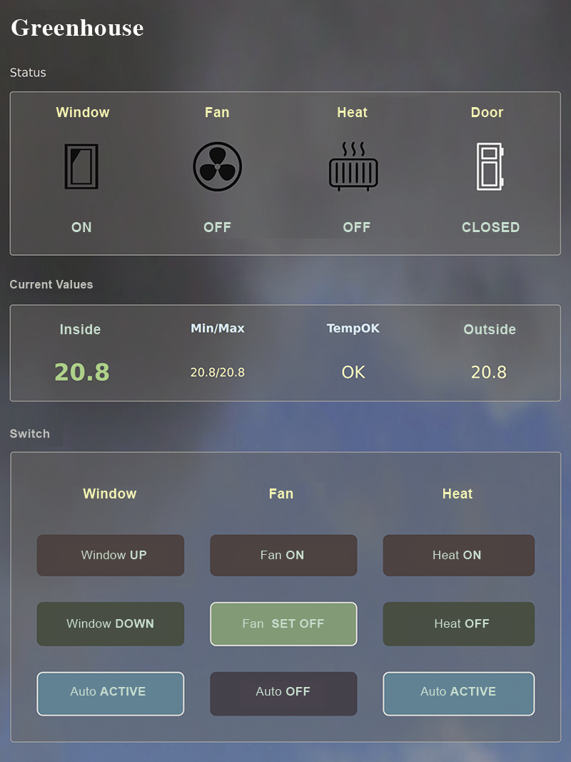
The app’s functions are:
- Immediate display of the current values
- Minimum/maximum temperatures and assessment of the operating status
- Manual switching of windows, fan, and heater
- Resetting variables to automatic control
- Displaying and deleting messages and error logs
- Daily and monthly charts of indoor/outdoor temperatures
- Reading and writing control parameters from and to memory
Because the Pico is always within range of my home WiFi network, I have the situation in the greenhouse constantly under control and can intervene by smartphone, tablet, or PC from the garden or apartment.
Conclusions
The greenhouse is in constant use from April to October. Accordingly, I want the electronic control system to be not only functional, but above all reliable in terms of operation. To protect the crops, it is advisable in a project like this to test everything thoroughly, module by module, up front before putting anything into operation. Once you have installed the system outside, it can be difficult to access the individual components.
The new controller has been running for some time now and has demonstrably been a valuable asset in the greenhouse thus far (Figure 6). It is reassuring to know that everything is well taken care of in my absence. Sometimes it’s the little things that matter, like the LED lights that let you know whether everything is OK as you walk past the greenhouse. In the next stage of expansion, I want to add moisture sensors so that I can also monitor the soil. You will find the software and full details of the project online, as well as on my GitHub site.