Code Blocks
Block coding is not exactly new, but block programming of a microcontroller is more exciting than you might think.
As the name suggests, PictoBlox is a block-based development environment. What’s unusual about it is the option to upload programs directly to an MCU. I will be looking at an example to discover how to implement projects with PictoBlox.
You can download the development environment free of charge from the manufacturer’s homepage; different versions are available for all common operating systems. As the current 7.1.0 version refused to compile programs for the ESP32 on Ubuntu, I went for the slightly older 6.2.0 version in my lab. After downloading the right installation package, install it on your computer with the following command:
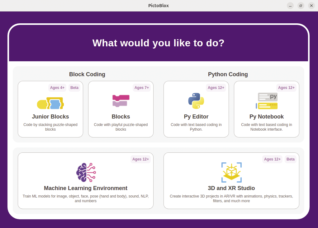
sudo dpkg -i PictoBlox6.2.0amdx64linux.debYou can use the pictoblox command to launch the IDE. To get started, first select the programming language (Figure 1) for your project – block coding in this case.

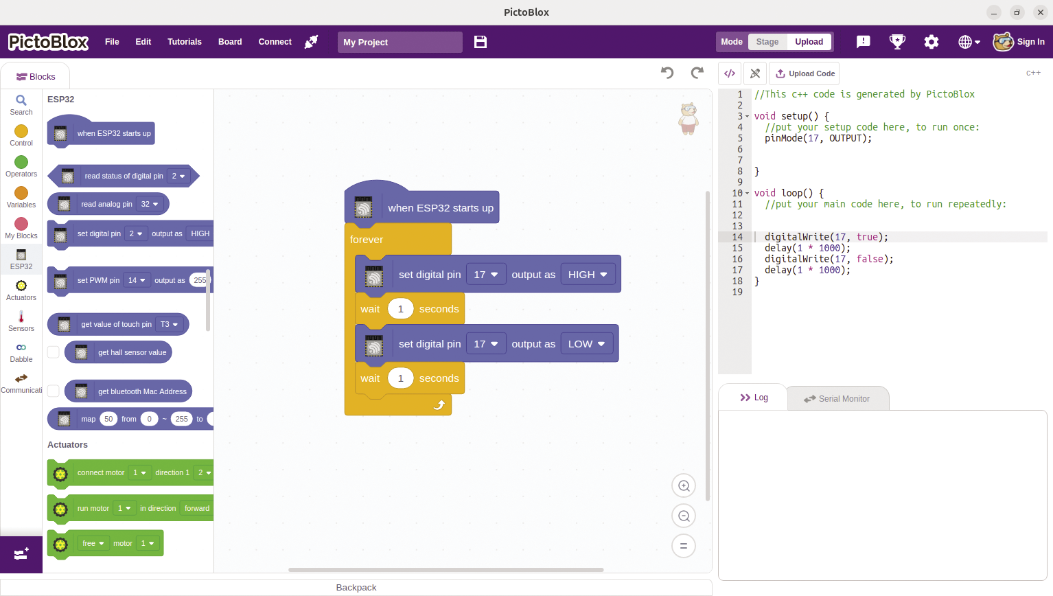
Before you start programming the microcontroller, you need to configure a few things as preparation. First of all, choose the ESP32 as the Board. Then specify the port to which the ESP32 is connected in Connect. Finally, select Upload top right. You will then find a block named when ESP32 starts up in the Blocks section.
Figure 2 shows a simple program that causes an LED on GPIO port 17 to flash. It is interesting to note that you can see the C/C++ code represented by the blocks in the middle in the section on the right. You can even edit the code by clicking on the pencil symbol (edit mode). But beware: If you change the blocks, your modifications of the C/C++ code will be overwritten without any warning. To upload the program to the ESP32, click the Upload Code button.

Test Setup
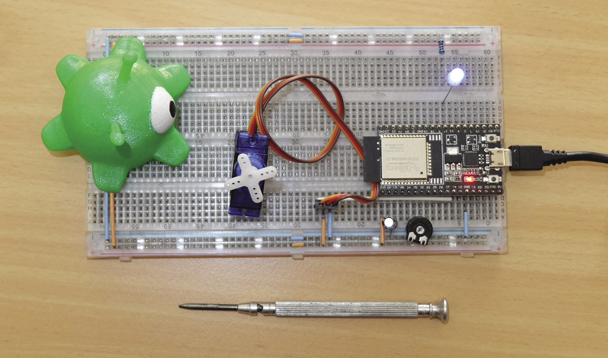
My test setup uses a simple example to illustrate what you can do with a block-based programming language. The idea is to read an analog value and use this value to move a servomotor. I also want the LED to flash at the same time. Figure 3 shows the test setup.

I’ve patched the potentiometer to pin 32 of the ESP32 and wired the other two connections to 3.3V and GND (ground), respectively. The servomotor’s signal input is connected to pin 14. Make sure that you supply the correct voltage for your choice of servomotor. I still need the LED on PIN 17. It requires a series resistor to work. I would typically go for a 1kOhm resistor to avoid the LED being unpleasantly bright. You now have everything you need for a test setup.
Don’t forget the capacitor between the analog output (EN) and GND. It ensures that you can always upload new code to the ESP32. Without the capacitor, you sometimes have to manually set the ESP32 to the right mode at the right time, and this can be annoying in the long term.
Program
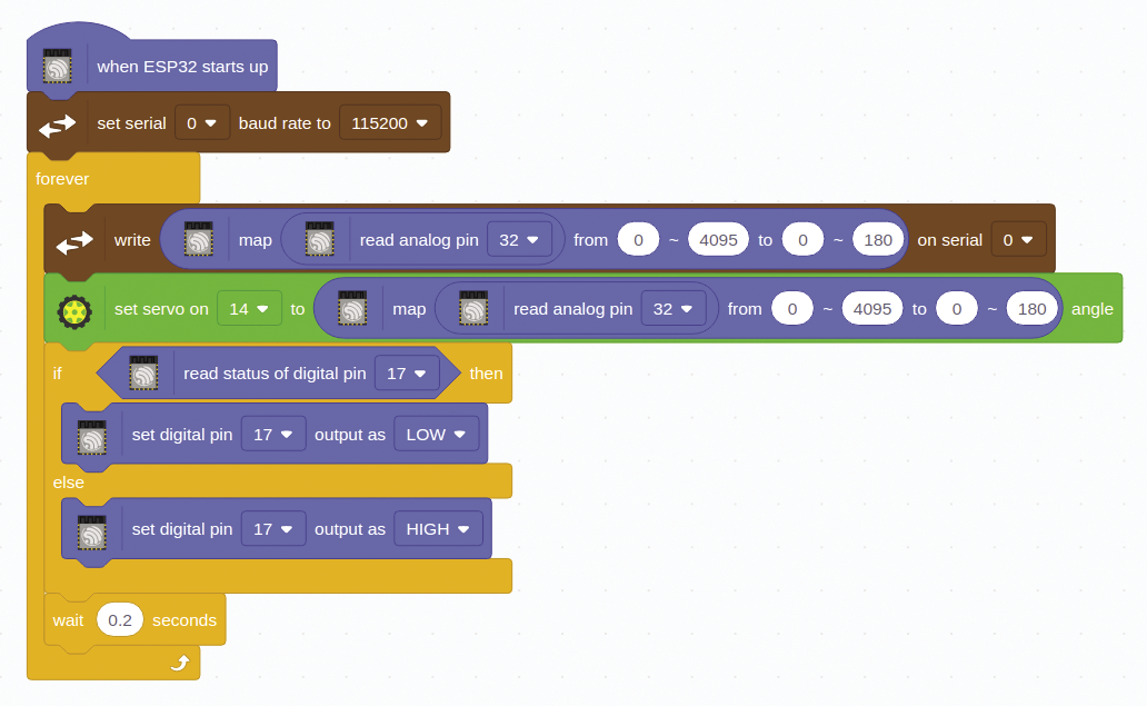
Although the program in Figure 4 appears to be self-explanatory at first glance, you still need to understand what exactly is happening. After starting the program, you first initialize the serial console so that you can check out what the program is doing at the moment. The console tends to crash and not display any output. In this case, you will need to briefly disconnect the ESP32 and reconnect it to the USB port.

The forever block is self-explanatory, but the blocks that follow are not quite as easy to understand: You need to dig a little deeper here. The ESP32 has a 12-bit analog-to-digital (AD) converter, which gives it a capacity of 4,096 digital values. These digital values now have to be translated into analog angle values from 0 to 180 degrees; the servomotor needs these to move to the desired position. This is the task that the map block handles. You just feed in the value to be converted along with the matching intervals (from, to). This ensures that the values are always in the correct range. The values are also output on the console so that you can check them. The next block sends them to the servo, and lo and behold, the servo moves to the position specified by the potentiometer.
The next code block is easy to explain: If the LED is off, it is switched on. If it is already lit, it is switched off. Basically, this block is no more than a complicated NOT condition. You need it here because you cannot assign a variable to the digital output. There is also a short wait defined right at the very end of the forever block. There are several reasons for this: The time specifies the frequency for the LED, it slows down the execution of the program, and this also reduces the amount of output on the console, which means that it is less likely to hang. On top of this, it avoids the servo drive constantly receiving new values that it has to move to. The AD converter output tends to fluctuate slightly, which explains the many different values.
Conclusions
PictoBlox is ideal for newcomers to microcontroller programming. The setup with the ESP32 is comparatively inexpensive and the software comes free of charge. Projects like this are a good way to combine electronics and programming basics. One particular highlight is that you can always see the generated C/C++ code, which makes it far easier to switch to an IDE such as Arduino or ESP-IDF later on.
Admittedly, PictoBlox has a number of pitfalls that users will have to get used to. If you already have some experience in programming microcontrollers, you will very quickly reach PictoBlox’s limits. Despite this, I hope you will enjoy experimenting with block-oriented programming on microcontrollers.


