
Under Control
Upgrade your computer with LEDs, buttons, or sensors to control a microcontroller board over USB from your web browser.
Microcontroller boards such as Arduino, Raspberry Pi Pico, and ESP32 can be connected to various LEDs, buttons, and sensors. Many of these boards have a built-in WiFi chip, which allows for remote control. However, sometimes WiFi is not possible, too complicated, or simply unnecessary.
Fortunately, most microcontroller boards for makers are equipped with a universal serial bus (USB) connection, which can often be used to send commands to the microcontroller from your computer or to receive sensor data. In this article, I explore what you need to establish two-way communication over USB, and I guide you through writing the necessary code for both the microcontroller and the computer.
USB CDC
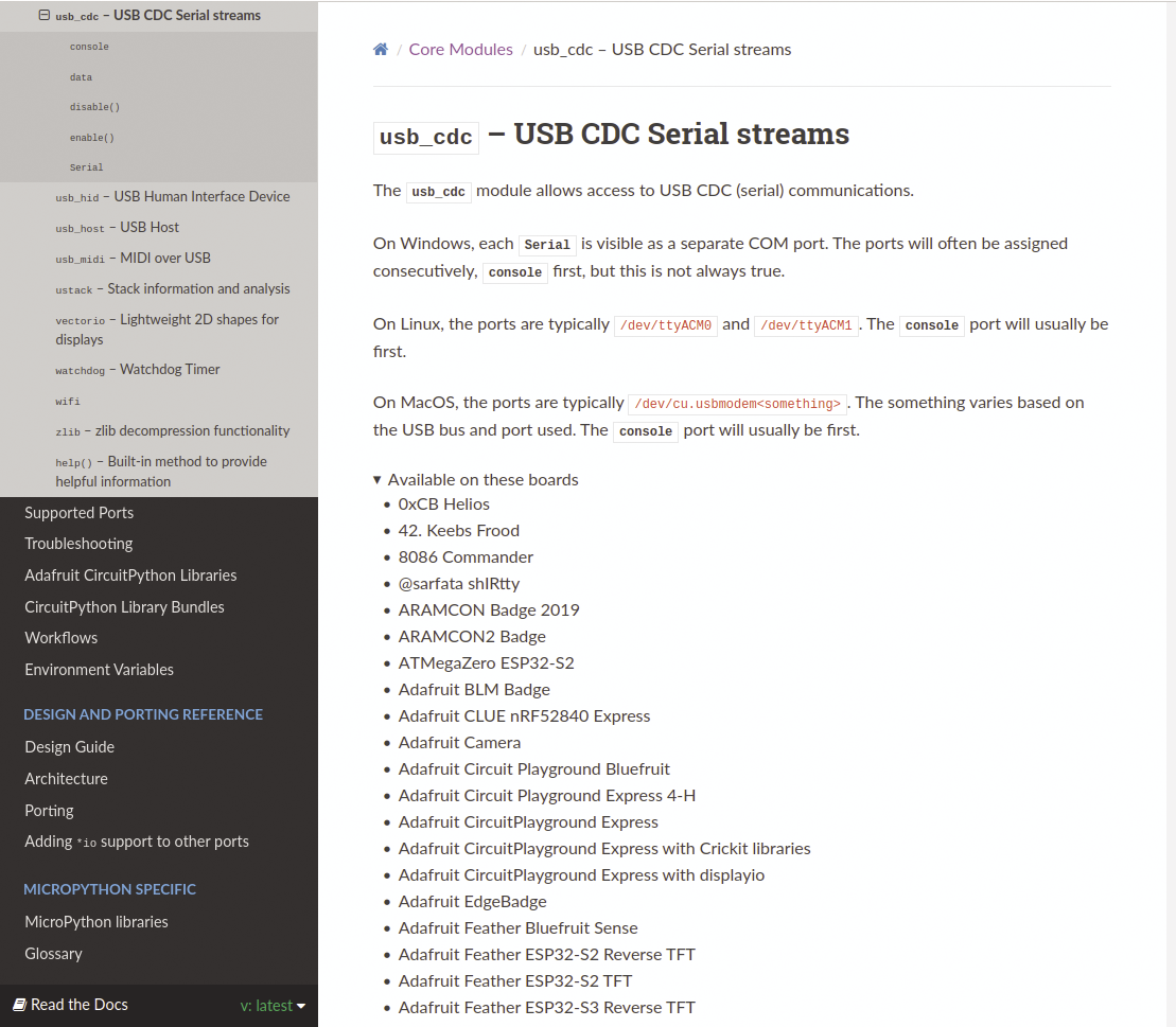
To enable communication between the microcontroller and computer, this project uses USB communications device class (CDC). When you connect a USB CDC device to your computer, this interface appears in your Linux system as a device, like /dev/ttyACM0. With this device file, software on your computer can communicate with the microcontroller.
Therefore, you need to establish a serial connection over USB CDC on the microcontroller. In this article, I do this with CircuitPython, which supports hundreds of microcontroller boards. Make sure to choose a board with USB CDC support (Figure 1). I have successfully tested this project with the Raspberry Pi Pico (W), Arduino Nano RP2040 Connect, Seeed Studio XIAO SAMD21, and Seeed Studio XIAO nRF52840. For other boards, you might need to modify the CircuitPython code slightly or install the firmware differently.
Installing CircuitPython
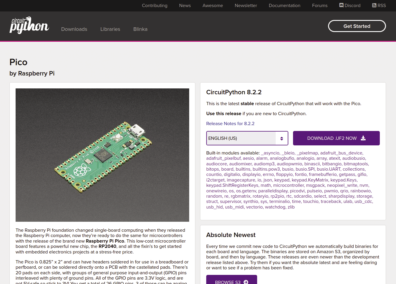
Note that you don’t need a board with WiFi or Bluetooth Low Energy (BLE) connectivity for serial communication, so you can choose a more affordable board, such as the Raspberry Pi Pico (the version without WiFi), which I use for the examples in this article. To download the appropriate CircuitPython firmware, visit the CircuitPython Downloads page and choose the link for your board.
At the time of writing, the Raspberry Pi Pico version was 8.2.2. You can choose your language, but that doesn’t matter much. On the device’s download page (Figure 2), you’ll see that the list of built-in modules includes usb_cdc, which confirms that you can use USB CDC on this board.
For the Raspberry Pi Pico, the downloaded firmware file has the .uf2 extension. To install the firmware, press and hold the white BOOTSEL button on the Raspberry Pi Pico, connect the board to your computer with a micro-USB cable, and then release the button. The board’s internal storage will now appear as a USB drive named RPI-RP2 on your computer. Drag and drop the .uf2 file onto that drive. After copying, the drive’s name will change to CIRCUITPY.
Mu Editor
The easiest way to program your board in CircuitPython is with the code editor Mu. You can download a TAR archive of an AppImage for Linux, currently at version 1.2.0. To untar the AppImage and make the file executable, run the following command:
tar xf MuEditor-Linux-1.2.0-x86_64.tar
chmod + x Mu_Editor-1.2.0-x86_64.AppImage
On most Linux distributions, you can now simply double-click the AppImage file in your favorite graphical file manager to start Mu. Detailed installation instructions for Mu for various distributions can be found on the website.
After launching Mu, click Mode at the top left, choose CircuitPython from the list, and click OK. If you connect your board to your computer with a USB cable, Mu should detect it, displaying the message Detected new CircuitPython device at the bottom.
Now you can type the code you want to run on your board in the large text field. To test the hardware to make sure it is working properly, enter the code in Listing 1, which makes the built-in LED blink.
Listing 1: Blink the LED
"""Make the built‑in LED blink."""
from board import LED
from digitalio import DigitalInOut, Direction
from time import sleep
led = DigitalInOut(LED)
led.direction = Direction.OUTPUT
while True:
led.value = True
sleep(0.5)
led.value = False
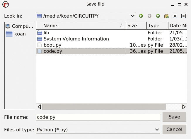
sleep(0.5)At the top, click Save, select code.py (Figure 3), and confirm that you want to overwrite it. You should now see the built-in LED on the Raspberry Pi Pico blinking, confirming that the board is working.
Defining a Protocol
Before programming the Pico, it’s important to establish a communication protocol between the microcontroller and the computer. Such a protocol is essentially a set of agreements for communication. What kind of communication does the microcontroller expect, and how does it respond to different commands? For the purpose of this example, I’ll keep the protocol simple. Each command sent to the microcontroller over USB consists of a single character that corresponds to an action to be performed on the built-in LED, as listed in Table 1.
Table 1: Serial Communication Protocol
|
Character |
Action |
|
0 |
Turn off LED |
|
1 |
Turn on LED |
|
2 |
Toggle LED |
|
3 |
Flash LED briefly |
After executing each command, the microcontroller should reply to the computer with the current state of the LED: 0 if the LED is off, and 1 if the LED is on.
Finally, note that I’m talking about characters here (letters, or in this case numbers), whereas serial communication operates on bytes. Therefore, the characters need to be converted to the corresponding bytes on both the computer and the microcontroller. For example, the character 1 is represented by 0x31 in hexadecimal notation.
Waiting for Commands
Now that the communication protocol between the microcontroller and computer is defined, you can program the CircuitPython code accordingly. As a first step, create a new file in Mu and add:
import usb_cdc

# Enable console-over-serial and data-over-serial
usb_cdc.enable(console=True, data=True)
This code enables data transfer over USB CDC.
By default, CircuitPython only uses USB CDC for the REPL (read-eval-print loop), which allows you to run Python commands over the USB connection (console=True). Adding data=True also sets up USB CDC for your own data channel.
If you save this file as boot.py, CircuitPython will execute it immediately after booting the microcontroller and before running any other code. Next, replace the existing code in code.py with the code in Listing 2.
Listing 2: code.py LED Control
01 from board import LED
02 from digitalio import DigitalInOut, Direction
03 from time import sleep
04 import usb_cdc
05
06 led = DigitalInOut(LED)
07 led.direction = Direction.OUTPUT
08
09 # Get the USB data feed object
10 serial = usb_cdc.data
11
12 while True:
13     # Check for incoming data
14     if serial.in_waiting > 0:
15         command = serial.read(1)
16
17         # Process command
18         if command == b"0":
19             led.value = False
20         elif command == b"1":
21             led.value = True
22         elif command == b"2":
23             led.value = not led.value
24         elif command == b"3":
25             led.value = not led.value
26             sleep(0.20)
27             led.value = not led.value
28
29         # Return state of LED
30         if led.value:
31             serial.write(b"1")
32         else:
33             serial.write(b"0")
This code starts by obtaining the serial object for the data, usb_cdc.data, and storing it in the variable serial. In an infinite loop (while True), it checks to see whether any data has come in on the serial interface from the computer. If it has, it reads one byte with serial.read(1) (line 15), then compares this byte with the values defined in the protocol.
Because the communication protocol deals with bytes, the program needs to convert the characters to bytes. For example, the code compares the received byte with b"0", which is the byte representation of character 0. It then turns the LED off or on accordingly.
Lines 23, 25, and 27 toggle the LED. Flashing the LED is achieved by toggling it, sleeping for a short time (200ms), and then toggling it again. Finally, the code writes the state of the LED to the serial interface with serial.write, so the computer can read its state. Save this file as code.py. The microcontroller is now waiting for commands.
Giving Commands
If you have been paying attention, you might have noticed that connecting your Pico to the computer now results in two serial devices appearing on your Linux system: /dev/ttyACM0 and /dev/ttyACM1. The console port for the REPL usually appears as the first listed, whereas the data port that you enabled in boot.py is typically the second listed. You’ll use this second port, /dev/ttyACM1, to communicate with the Pico from your computer.
To give these commands, simply open a terminal window and run screen:
screen /dev/ttyACM1
As soon as you press one of the keys for the characters 0, 1, 2, or 3, the Pico responds with the corresponding action and returns the state of the LED as a 0 (off) or 1 (on). You do not need to press Enter. If you type anything other than the four characters defined in the protocol, the Pico simply replies with the current state of the LED: 0 or 1. (See the “Expand the Possibilities” box.)
For simplicity, I have limited the example code to recognize only four commands. However, you can easily define a more complex protocol. For example, you can add a second character to the commands to choose a specific LED number, allowing you to control multiple LEDs, or you can define additional commands to set the color of an LED, enabling control of multiple RGB color LEDs. Try expanding the code in this article to take advantage of the full potential of your microcontroller and computer.
To close the serial connection in the screen session, just press Ctrl+A and then a backslash (\). Confirm that you want to terminate by typing y.
From Your Web Browser
Although the screen command is useful for testing, it’s not the most user-friendly interface. In the remaining part of this article, I demonstrate how to build a web-based interface for communication with your microcontroller and the Web Serial API. (See also the “Alternative Firmware and PC Software” box.) Note that this API is currently only supported in the Chrome or Edge web browsers.
In this article, I’ve demonstrated the microcontroller side with CircuitPython. However, you can achieve the same result with various other development platforms, such as Arduino code. For example, the small and cheap Digispark microcontroller board can communicate with your computer and the Arduino library DigiCDC. Although the original board is no longer manufactured, you can still find clones in various web shops. Numerous alternatives for Web Serial also exist for the software on the computer. For example, you can write a program in Python that communicates with the serial port and the pySerial library. You can even create a graphical interface with a toolkit such as Tkinter. As long as you ensure that both sides use the same protocol, the alternatives are interchangeable.
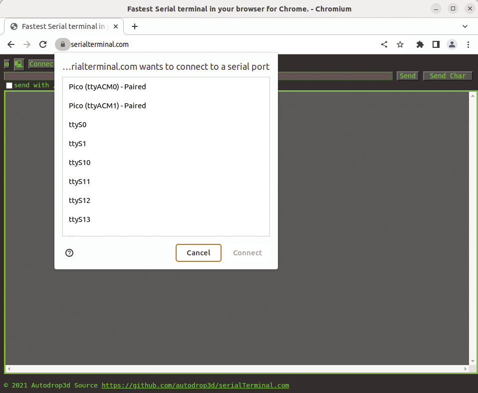
A simple implementation is a website called serialterminal.com. After visiting this website from a supported web browser, click Connect in the top left corner. Your web browser will then display a list of serial interfaces (Figure 4). Select the appropriate one (Pico (ttyACM1) – Paired) from the list and click Connect.
Make sure to uncheck the options send with /r, send with /n, and echo. You can then enter commands in the text field at the top. For example, type 1 and click Send on the right. The LED on your Pico should now turn on because the CircuitPython code running on the microcontroller recognizes the character 1 and reacts accordingly. Type 2 to toggle the LED, after which it will turn off. You will also see the output from the microcontroller in the large text field at the bottom: 1 if the LED is on and 0 if it is off.
Creating a Web Interface
Now that you know you are able to communicate with the board from a web page, you can create a more convenient interface in your own web applications to control the LED with the same Web Serial technology from the serialterminal.com website. First, create a simple HTML page with the code in Listing 3.
Listing 3: usb-led.html
01 <!DOCTYPE html>
02 <html lang="en">
03 <head>
04     <title>USB LED</title>
05     <style>
06         body {
07             font‑family: Arial, sans‑serif;
08             text‑align: center;
09             padding: 50px;
10         }
11         button {
12             font‑size: 24px;
13             padding: 10px 20px;
14             margin: 10px;
15         }
16         #lightbulbIcon {
17             font‑size: 32px;
18         }
19     </style>
20     <script src="usb‑led.js"></scriptv
21 </head>
22 <body>
23     <h1>USB LED</h1>
24     <button id="connectButton">Connect</button>
25     <button id="offButton">OFF</button>
26     <button id="onButton">ON</button>
27     <button id="toggleButton">TOGGLE</button>
28     <button id="flashButton">FLASH</button>
29*    <span id="lightbulbIcon">💡</span>
30 </body>
31 </html>
Note: In line 29 of Listing 3 the HTML should read like this:
<span id="lightbulbIcon">💡</span>
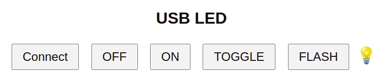
This web page has buttons to connect, turn off, turn on, toggle, and flash the LED. It also displays an icon of a light bulb (in the form of an emoji) to represent the state of the LED (Figure 5).
JavaScript Code
The HTML page includes the usb-led.js file as a script. This file contains the code in Listing 4 to send commands to the connected microcontroller by the Web Serial API.
Listing 4: usb-led.js
01 let lightbulbIcon;
02 let port;
03 let writer;
04
05 async function readState() {
06     const reader = port.readable.getReader();
07     const { value, done } = await reader.read();
08
09     const receivedByte = value[0];
10     if (receivedByte === '1'.charCodeAt(0)) {
11         lightbulbIcon.style.display = "inline";
12     } else if (receivedByte === '0'.charCodeAt(0)) {
13         lightbulbIcon.style.display = "none";
14     }
15     reader.releaseLock();
16 }
17
18 async function writeCommand(command) {
19     if (!writer) return;
20
21     const data = new TextEncoder().encode(command);
22     await writer.write(data);
23     await readState();
24 }
25
26 document.addEventListener("DOMContentLoaded", () => {
27     const connectButton =
document.getElementById("connectButton");
28     const offButton = document.getElementById("offButton");
29     const onButton = document.getElementById("onButton");
30     const toggleButton = document.getElementById("toggleButton");
31     const flashButton = document.getElementById("flashButton");
32     lightbulbIcon = document.getElementById("lightbulbIcon");
33
34     connectButton.addEventListener("click", async () => {
35         if (!navigator.serial) {
36             alert("Web Serial API not supported by this browser.");
37             return;
38         }
39
40         try {
41             port = await navigator.serial.requestPort();
42             await port.open({ baudRate: 9600 });
43             writer = port.writable.getWriter();
44
45             connectButton.disabled = true;
46         } catch (error) {
47             console.error("Error:", error);
48         }
49     });
50
51     offButton.addEventListener("click", async () => {
52         await writeCommand("0");
53     });
54
55     onButton.addEventListener("click", async () => {
56         await writeCommand("1");
57     });
58
59     toggleButton.addEventListener("click", async () => {
60         await writeCommand("2");
61     });
62
63     flashButton.addEventListener("click", async () => {
64         await writeCommand("3");
65     });
66
67 });
The JavaScript code comprises functions to read the state of the LED from the microcontroller and to write commands to control the LED. The readState function reads a byte from the serial interface and updates the light bulb icon to be visible if the byte corresponds to the character 1 or to be hidden if it corresponds to the character 0. The writeCommand function (lines 18-24) writes a command to the serial interface and then reads the LED state by calling the readState function.
The remaining code is executed after the Document Object Model (DOM) has fully loaded, adding event listeners to all the buttons. When you click Connect, the port is chosen by the Web Serial API. Clicking on the other buttons calls the writeCommand function with the corresponding command.
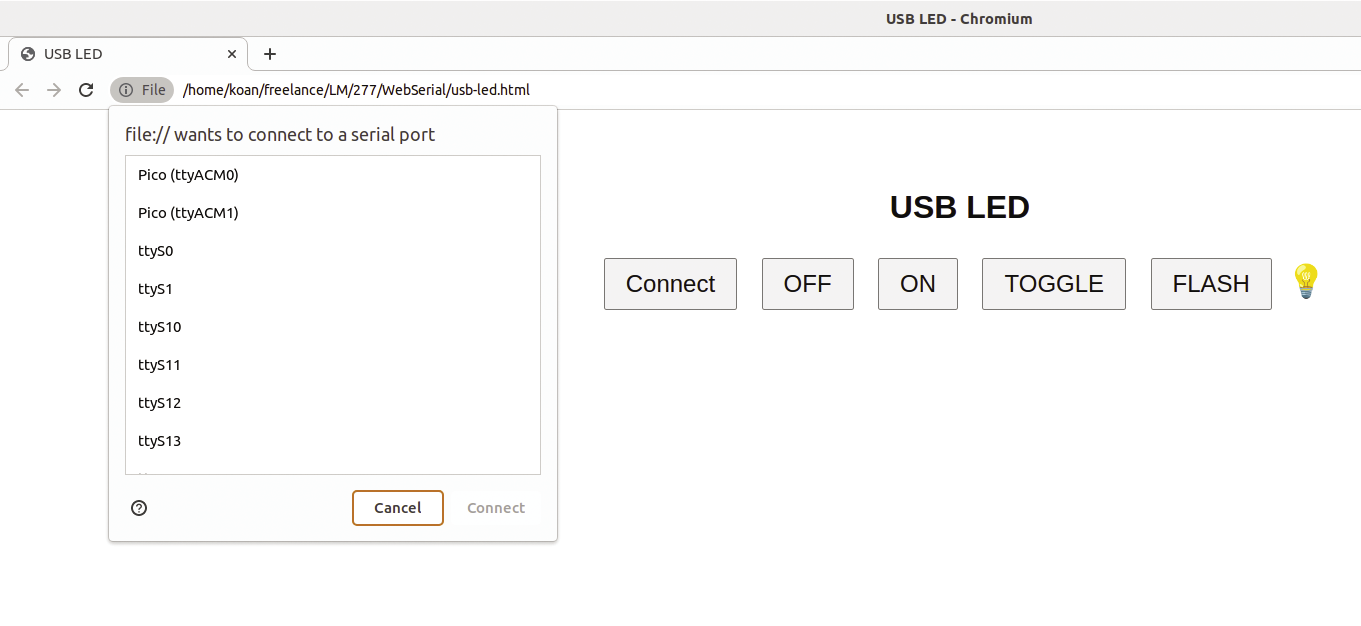
To use this web interface, open the HTML page in Chrome, make sure your Pico is connected, and click Connect. Choose the correct port (Figure 6) and try out the different buttons to control the LED on the Pico. The light bulb will disappear when you turn off the LED and reappear after turning it on.
Temperature Sensor
Similarly, you can connect a temperature sensor to the Raspberry Pi Pico and have it send measurements to your computer over USB. For this example, I chose the popular BME280 temperature sensor made by Bosch – specifically, Adafruit’s breakout board with the sensor. Cheaper versions are available from Chinese manufacturers, but make sure it is an I2C version that operates at 3.3V.
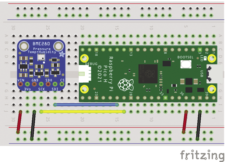
Disconnect the USB cable from the Pico and place the board on a breadboard. Connect SDA (SDI on the Adafruit board) to pin 26 (GP20) of the Pico, SCL (SCK on Adafruit) to pin 27 (GP21), VCC (Vin on Adafruit) to 3.3V, and GND to GND (Figure 7). If you are unsure about the correct pins on the microcontroller board, refer to the Raspberry Pi Pico Pinout website . After connecting all the wires, reconnect the Pico to USB.
Next, download Adafruit’s CircuitPython Library Bundle for CircuitPython 8.x, extract the ZIP file, go into the lib directory, and copy the adafruit_bme280 and adafruit_bus_device directories to the lib directory of your CIRCUITPY drive to install the CircuitPython driver for the BME280.
Sending Temperature Measurements
Next, modify the code in code.py in the Mu editor to read the temperature and humidity continuously from the sensor and send them through the serial interface (Listing 5).
Listing 5: code.py Temperature Sensor
from time import sleep
import board
import busio
from adafruit_bme280.basic import Adafruit_BME280_I2C
import usb_cdc

i2c = busio.I2C(scl=board.GP21, sda=board.GP20)
bme280 = Adafruit_BME280_I2C(i2c)
serial = usb_cdc.data

while True:
    temperature = round(bme280.temperature, 1)
    serial.write(str(temperature).encode("utf‑8"))
    serial.write(b"\n")
    sleep(1)
First, the code sets up the I2C bus, defining the appropriate GPIO pins for SCL and SDA. Next, it initializes the Adafruit BME280 driver. By default, the library uses the sensor with I2C address 0x77. If your BME280 uses address 0x76, specify this as an argument when initializing the driver:
bme280 = Adafruit_BME280_I2C(i2c, address=0x76)
The next line obtains the data connection for the serial interface. Finally, the program starts an infinite loop that reads the temperature from the sensor, rounds it to one decimal place, writes it to the serial interface as a string encoded in UTF-8 followed by a newline character, and sleeps for one second.
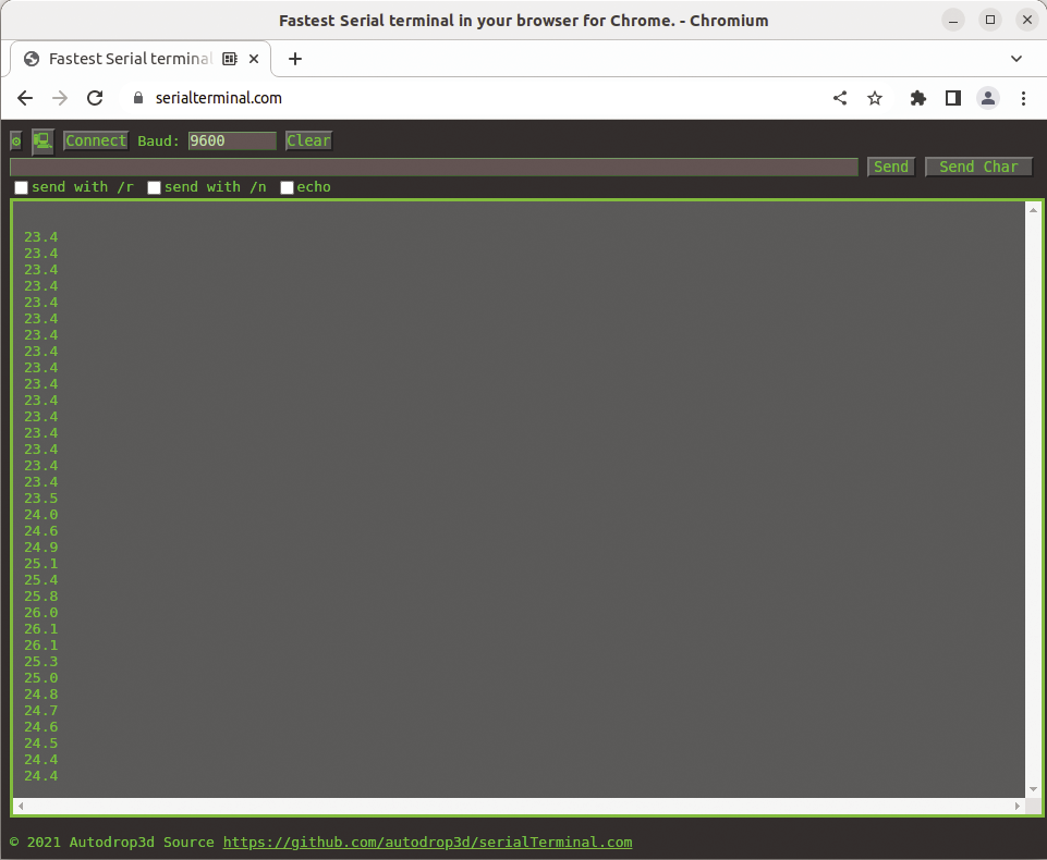
Save this code as code.py and connect to the Pico’s /dev/ttyACM1 device with screen in the terminal or serialterminal.com in Chrome. You’ll see the temperature measurements scrolling by (Figure 8), each measurement on a new line because of the "\n" newline character.
Sensor Measurements in HTML
To display the sensor measurements in a web interface, you can create a simple HTML page, like that shown in Listing 6. This page only contains a button to establish the serial connection and a span element to display the temperature. The corresponding JavaScript file shown in Listing 7 is also straightforward.
Listing 6: usb-bme280.html
01 <!DOCTYPE html>
02 <html lang="en">
03 <head>
04 <title>USB Temperature</title>
05     <style>
06         body {
07             font‑family: Arial, sans‑serif;
08             text‑align: center;
09             padding: 50px;
10         }
11         button {
12             font‑size: 24px;
13             padding: 10px 20px;
14             margin: 10px;
15         }
16         .measurement {
17             font‑size: 24px;
18             padding: 10px 20px;
19             margin: 10px;
20         }
21     </style>
22     <script src="usb‑bme280.js"></script>
23 </head>
24 <body>
25     <h1>USB Temperature</h1>
26     <button id="connectButton">Connect</button>
27     <p class="measurement"><span id="temperature">TODO</span> °C</p>
28 </body>
29 </html>
Listing 7: usb-bme280.js
01 document.addEventListener("DOMContentLoaded", () => {
02 const connectButton = document.getElementById("connectButton");
03 const temperatureSpan = document.getElementById("temperature");
04
05 connectButton.addEventListener("click", async () => {
06 if (!navigator.serial) {
07 alert("Web Serial API not supported by this browser.");
08 return;
09 }
10
11 try {
12 port = await navigator.serial.requestPort();
13 await port.open({ baudRate: 9600 });
14 connectButton.disabled = true;
15
16 const textDecoder = new TextDecoderStream();
17 const readableStreamClosed = port.readable.pipeTo(textDecoder.writable);
18 const reader = textDecoder.readable.getReader();
19
20 // Listen to data coming from the serial device.
21 while (true) {
22 const { value, done } = await reader.read();
23 if (done) {
24 // Allow the serial port to be closed later.
25 reader.releaseLock();
26 break;
27 }
28 // Remove carriage return and newlines from string
29 temperature = value.replace(/[\r\n]+/g, "")
30 if (temperature.length > 0) {
31 temperatureSpan.textContent = temperature;
32 }
33 }
34 } catch (error) {
35 console.error("Error:", error);
36 }
37 });
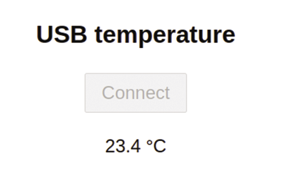
38 });After the DOM has loaded, the JavaScript code adds an event listener to the Connect button. Once you have clicked on the button and the serial connection is established, the code continuously reads a text stream. Each time a line of text is received, it updates the span element with the ID temperature, updating the temperature continuously on the web page (Figure 9).
Improvements
This project has many areas for improvement. For example, you can convert the temperature sensor measurements from degrees Celsius to degrees Fahrenheit, read the humidity from the sensor and display it in another text box on the web page, and improve the look of the layout with a stylesheet.