Wiggle Time
You can take lenticular images with a homemade camera to recreate the “wiggle” pictures of your childhood.
Lenticular images store multiple exposures in the same area. Animation is achieved by tilting the image. Another application creates a spatial appearance without special tools (autostereoscopy). The digital version of this often shows up on social media as a “wigglegram.”
Lenticular Cameras
On the consumer market, lenticular cameras are sold under the name ActionSampler. More than 40 years ago, the four-lens Nishika (Nimslo) appeared, followed by Fuji’s eight-lens Rensha Cardia in 1991. Unlike the Nishika’s synchronous shutter action, the Fuji exposed the 35mm film sequentially. Even today, the analog scenes are still very popular on Instagram and the like.
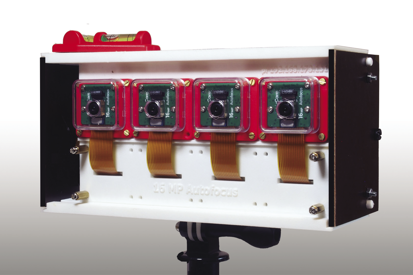
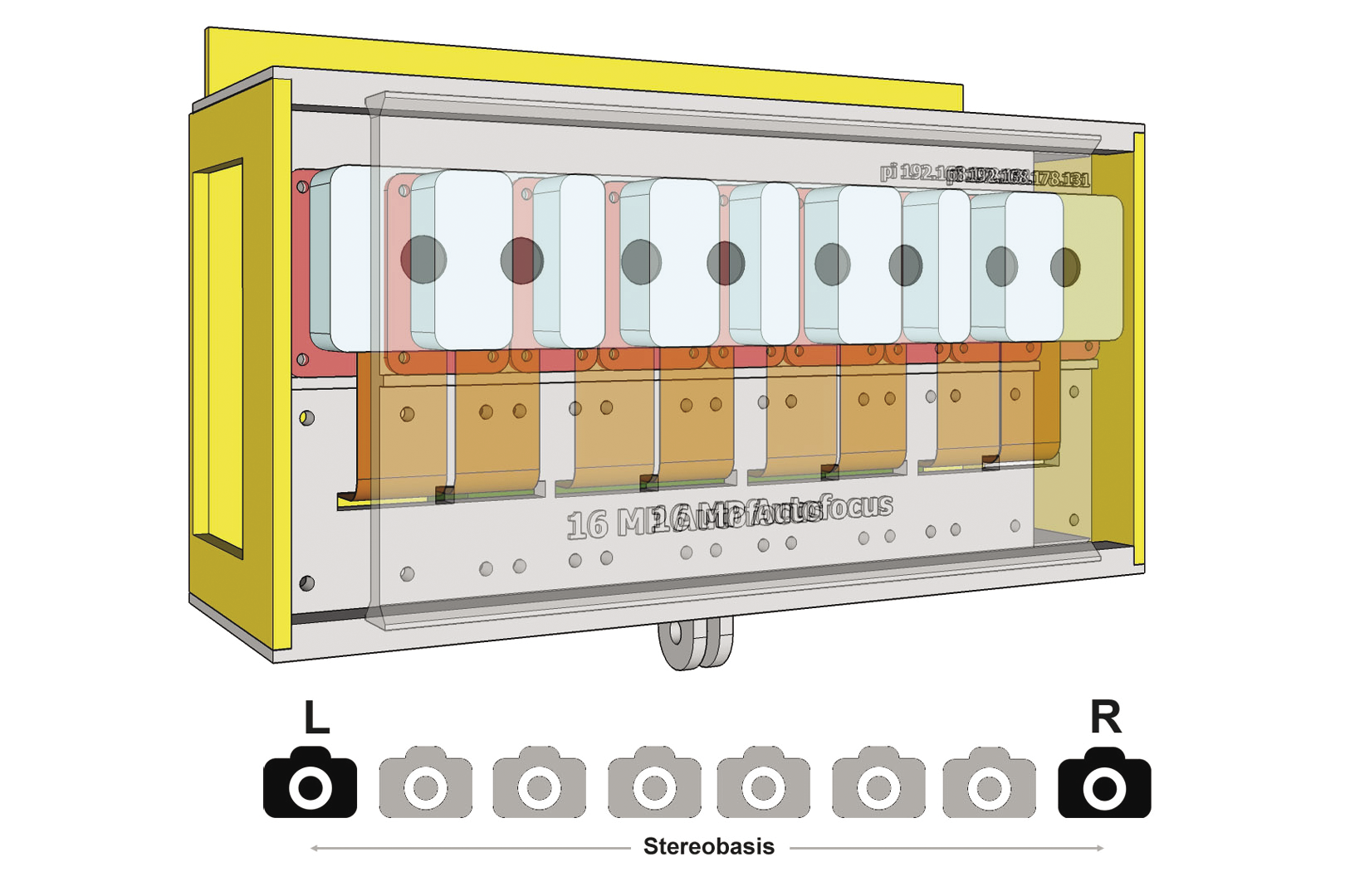
One way of creating a multilens digital recording system is to use a Raspberry Pi and a Camarray HAT (hardware attached on top) by ArduCam. The camera I make in this article uses four Sony IMX519 sensors arranged at a distance of 4cm apart (Figure 1). After the first exposure, you can move the device by half the camera distance, which produces eight shots of a subject at equal distances with a total of 32 megapixels (MP).
Lenticular Technology
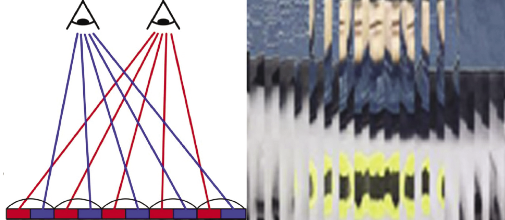
The predecessors of today’s lenticular screens are corrugated and lamellar screens that take two and three displayable images, respectively. Unlike the planar image strips of their predecessors, the lens screens commonly used today are transparent films of semi-cylindrical strips that show multiple images simultaneously. Depending on the viewer’s angle of view, the left eye sees something different than the right eye, and the viewer perceives the view as three-dimensional (Figure 2).
The lenses differ in terms of thickness and curvature radius; resolution is stated in lines per inch (lpi). Changing the image, animation, and zooming and morphing effects can be achieved with image strips arranged horizontally. To separate spatial images you need vertical image strips; the input images are encoded strip by strip in line with the lens spacing and are printed on a self-adhesive foil or as mirror images on the reverse side of the foil.
You can achieve a spatial vision effect by nesting the individual images inside each other, which leads to image separation for the viewer. However, you do not need to restrict yourself to two images; instead, you can compile a series of images. To do this for static scenes, you move the camera step-by-step. Alternatively, you can use camera technology with multiple lenses, which is also how to capture dynamic scenes. StereoPhoto Maker is freeware for preparing image series. If you want to look more closely into wigglegrams, it is a good idea to take a look at the Triaxes 3DMasterKit software.
Four-Lens DIY Camera
As the control unit, I will add the ArduCam Camarray HAT to a Raspberry Pi 4B. The Pivariety manufacturer makes extended solutions for Raspberry Pi standard cameras that act as Video for Linux version 2 (V4L2) devices. The HAT operates four Sony IMX519 sensors over a Camera Serial Interface (CSI), which you address on the I2C bus. The sensors have an image memory of 16MP, but depending on the addressing, one or more sensors share the image memory. The sensors can be operated in autofocus mode or with manual adjustment. The field of view is 80 degrees horizontally, and sharpness starts at about 8cm.
While you are on the move, a 5V power bank supplies the unit with energy. Three-dimensional printed components let you design a case. The camera boards sit side by side in the supplied brackets. Of course, you can’t adjust a setup like this with single-pixel accuracy, but you don’t need that because you can use the application software instead. The housing is designed so you can move the entire lens board by half the camera distance. In this way, the data for a lenticular image can be assembled from eight exposures, each 2cm apart over a base of 14cm.
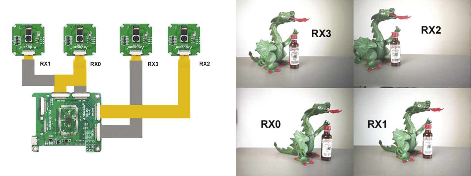
The multicamera adapter is connected to the sensors by four interfaces that use ribbon cables. You then need to connect it to the computer on the CSI interface. Three spacer screws secure the mechanical connection to the Raspberry Pi; the 5V power supply comes through the GPIO pins. How you arrange the cameras is entirely up to you. The boards each come in a small case, and you install them 40mm apart. If you do not use the housings, the minimum distance is reduced to 24mm. The software addresses the sensors as a single frame. By setting the corresponding I2C parameters, you can configure one, two, or four sensors. The cameras always have to share the available resolution.
The default is
i2cset -y 10 0x24 0x24 0x00(i.e., Quadro mode). Accordingly, the resolution for each image is restricted to a maximum of 2328x1746 pixels, and synchronization is in pairs at frame level. If you use the following parameters:
i2cset -y 10 0x24 0x24 0x01the result is a resolution of two times 2328x3496 pixels in dual mode, which is extrapolated to two times 4656x3496 pixels later in the application. You may already be familiar with image compression from stereoscopy.
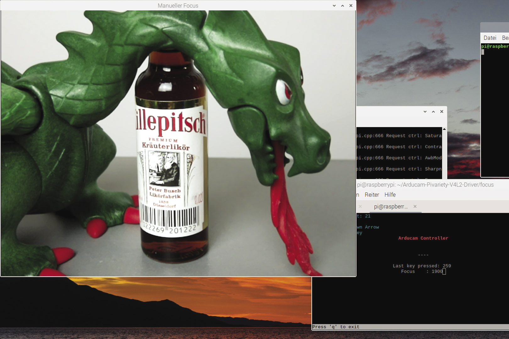
The images in Figure 3 on the right were taken from close up and therefore clearly reflect the camera layout and cabling (from left to right: RX2, RX3, RX1, and RX0). Despite the convenient autofocus mode, it is important not to forget the manual focus options. Especially at close range, manual focus results in some interesting photographic options (Figure 4).
Installing the Camarray HAT
You can install the required applications and the driver for the quad kit with the shell script install_pivariety_pkgs.sh (Listing 1). More information is available in the ArduCam documentation.
Listing 1: Installing the Camarray HAT
$ wget ‑O install_pivariety_pkgs.sh https://github.com/ArduCAM/Arducam‑Pivariety‑V4L2‑Driver/releases/download/install_script/install_pivariety_pkgs.sh
$ chmod +x install_pivariety_pkgs.sh
$ sudo apt‑update
$ ./install_pivariety_pkgs.sh ‑p libcamera_dev
$ ./install_pivariety_pkgs.sh ‑p libcamera_apps
$ ./install_pivariety_pkgs.sh ‑p imx519_kernel_driver_low_speed
[...]
$ libcamera‑still ‑‑list‑cameras
  0 : imx519 [4656x3496] (/base/soc/i2c0mux/i2c@1/imx519@1a)
  Modes: 'SRGGB10_CSI2P' : 1280x720 1920x1080 2328x1748 3840x2160 4656x3496
After the libcamera-hello command, the camera will respond for a short while. The
libcamera-still --list-cameras
command (Listing 1, last command) checks which cameras are connected. As mentioned before, the software identifies the four sensors as a single device.
Libcamera
The release of the Raspberry Pi OS “Bullseye” operating system in November 2021 fundamentally changed the handling of the camera module. Brand new libcamera commands have since replaced the tried and trusted command-line tools raspistill and raspivid. You can still use raspistill in legacy mode, but makers with more ambitious goals need to get comfortable with the libcamera library.
The transition of the camera control to the Linux kernel’s Libcamera driver ensures a standards-compliant solution without proprietary code. New commands such as libcamera-still or libcamera-vid are available, and you can build your own apps on the Libcamera code. Extensive documentation can be found on the Raspberry Pi Foundation website.
If you have already worked with raspistill or raspivid, it should not be difficult to come to grips quickly with Libcamera. The sample code
$ i2cset -y 10 0x24 0x24 0x00
$ libcamera-still -t 30000 --ev -5 --gain 8 --roi 0,0,1,1 --autofocus --info-text "Killepitch" -o testQuadro.jpg
captures the entire image (region of interest, --roi) in autofocus mode after a preview time of 30 seconds (time out, -t) with an exposure compensation of -5 (exposure value, --ev). The --gain 8 parameter corresponds to an ISO value of 800, and the --info-text flag lets you manipulate the header in the application; the output file is assigned the name testQuadro.jpg (output, -o).
Shooting Lenticular Photos
The DIY camera is designed to be point-and-shoot, but the implementation is a little more modest because of the available technology. In my test environment, the system is connected to the local WiFi network behind a mobile router. After switching on the camera, the operating system boots and logs on to the WiFi network. The Virtual Network Computing (VNC) server starts up at boot time.
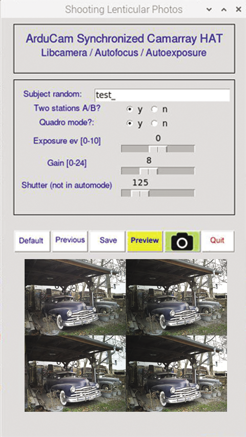
The same applies to the graphical user interface (GUI; Figure 5), with simple setup functions such as image name, shutter speed, exposure value, preview image, and shutter trigger. The GUI offers more functions, but I will not be using them for the time being. The software, written in Python, uses Guizero with object-oriented controls. It keeps its settings in a dictionary and uses system commands to call the camera functions (see also the “Graphical User Interface” box).
In the download section for this article you will find the
lentiCam.py GUI, which I programmed in Python. The dcim/ directory also contains some recent images as examples of the components of a lenticular image.The images for positions A and B and the individual image tiles end up in the dcim/randomCode/ directory with randomized image labels. The GUI displays the generated random code, which can be changed alphanumerically if required. You decide in advance whether you want to create two, four, or eight exposures. The camera settings can be saved so that you can reuse them for later shots. To align the camera, click the Preview button; status messages are displayed in the header.
Finding a shooting scenario is now the problem. The camera is oriented horizontally. By rule of thumb, the distance to the object is 30 times the distance from the right to the left camera (close-up distance 1/30). Intermediate images split this distance evenly, as you can see in Figure 6, working with four sensors at a distance of 12cm with two intermediate images. This results in a close-up distance of about 3.6m. If you move the lens board by 2cm, you end up with four shots at 8cm apart, and ideally approach the subject to within 2.4m.
These approximations are only rough, based on experience, and by no means binding. The close-up value could well be closer to 1/20 than 1/30. As soon as you move your camera between two positions, you are forced to limit your work to static objects. Manual exposure by shutter speed and gain settings is generally recommended.
After capturing an image, you then need to break the frame down into individual tiles for further processing with the help of the FFmpeg suite or ImageMagick tools, which you can install with:
sudo apt-get install imagemagick
sudo apt-get install ffmpeg
To ensure that the images are ordered correctly, add a numerical suffix in the file name.
Making One Out of Many
Once you have done the field work, you can continue processing the image series on the computer. Download the images with an FTP client; then, StereoPhoto Maker (for example) will give you all the functions you need for downstream processing. Triaxes is also a good choice for lenticular images. With just two exposures, you can create an anaglyph image for red and cyan glasses or a simple wiggle image. More uniform motion and lenticular images will always require a series of images.
To begin, get a series of eight images for a spatial image. The images must be aligned uniformly; even slight skew and small vertical differences will make the images unusable. In StereoPhoto Maker, select File | Multiple Images | Auto rotation adjustment and select the images to be adjusted. In the second step, you need a common reference point in each image. The function for this can be found in File | Multiple Images | X-Y adjustment and cropping.
Now you can print the image by selecting Edit | Create Lenticular Image. Set the Lenticular Lens Pitch and the printer resolution to match the lenticular film. Finally, print the image with File | Print preview. Lenticular film of 15x10cm is available with different lens spacings with vertical and horizontal alignment. You need to align the self-adhesive films over the printout and then carefully press them on. A laminator is useful for larger formats.
If you want to process the image series as a wigglegram, use the ImageMagick convert function. The following command adds all JPEGs with the image prefix in the current directory to the animated GIF:
$ convert -delay 10 -loop 0 image*.jpg <Wiggle>.gifThe playback is in an infinite loop at 10fps. The procedure depends on the size and number of images. Instead of a GIF, you can use the MP4 format. A wiggle cannot be printed, of course, so check out the examples online (German) if you need a visual reference.
The Triaxes 3DMasterKit, which is a commercial product, is a good choice for lenticular images. The license will not cost you much, and the investment is definitely worthwhile. After you upload the frames, you can reorder them and orient them alternately before cropping the images and computing the lenticular image. The kit also has other useful features, such as animations and layered 3D.
Conclusions
Lenticular images as analog 3D representations, and animations and wiggles for the Internet, give photographers a creative tool. Even with a conventional camera, you can achieve presentable results with a little practice.
The Camarray HAT by ArduCam lets you use a multisensor system in single, dual, or quadro mode and construct a DIY camera that suits your ideas. This hardware opens up a wide field of experimentation for amateur photographers, ranging from high-quality stereo images to low-resolution shaky images.
All you need for the build is a Raspberry Pi, a multicamera system, and a power pack. On the local WiFi network, a smartphone or tablet gives you a graphical user interface, and Python, Libcamera, and Guizero form the software underpinnings. StereoPhoto Maker and Triaxes take care of downstream processing.