
Clocking On
A few electronic components, some code, and a hand-made wooden case make a fine retro-style bedside clock.
When my venerable bedside clock radio and alarm – a present from my parents in the 1980s – finally died, as a maker, my first thought was not, “Where can I buy another?” but “Can I make one?”! I didn’t really use the radio (I think it was AM only, and here in the UK, AM is no longer used much), so my ideas began to form around a simple, retro-style digital clock with an LED display in an attractive wooden case.
The case needed to be simple to build because my woodworking skills are limited. I chose a large green LED display for its restful color in the dark, and I wanted the clock to run off a USB wall socket to simplify the power supply design whilst retaining the possibility of running from a small external USB battery pack. I felt some user interface would be required to set the time, set and cancel an alarm, and control the display brightness. Five push-buttons are sufficient for this task. The alarm, of course, requires a buzzer or speaker. Table 1 lists the essential hardware elements.
|
Components |
|
A microcontroller (32-bit ARM CPU, 48MHz internal clock) |
|
32KHz watch crystal for the real-time clock |
|
8MHz crystal for microcontroller |
|
Backup battery for the real-time clock |
|
Four seven-segment displays, one inch high, for hours and minutes |
|
Two discrete LEDs for the colon between hours and minutes |
|
Piezoelectric buzzer for alarm |
|
Four push-buttons to set time and brightness, one to cancel the alarm |
|
Connectors for power, programming, debugging |
Hardware Design
The core of the system is an STM32 microcontroller, specifically the STM32F072CBT6. It drives the display, interrogates the switches, and drives the buzzer for the alarm. You will find a huge variety of microcontrollers on the market, so the choice of an appropriate device can be daunting. Previous experience tells me that ST Microelectronics devices perform well at a good price point and are very well supported in terms of development tools and online resources. Having designed a great many projects around these devices, I also know that software development will be accelerated by my familiarity with the STM32 family and their development tools.
This project could just as easily have been based on an Arduino, a PIC, or a Pi Pico; however, as I say, choice comes down to familiarity and suitable package configurations with the required I/O. The key feature required for a clock is clearly a battery-backed real-time clock built into the microcontroller, and with ST Microelectronics’ excellent device selection tools, I was able to select a suitable device with this feature, as well as sufficient pins to drive the display, switches, buzzer, and debug port.
As you will see, onboard timers are key to this project and all STM32 devices come with several configurable timer units. The device needs an external crystal as a frequency source for the real-time clock, but in all other regards, is entirely self-contained. The frequency accuracy and temperature coefficient of this crystal will determine the overall accuracy of the clock, so it is important to choose this device carefully.
The project was designed to run from a standard USB socket, and the 5V provided powers the displays directly, whilst a small linear regulator provides the 3.3V supply to the microcontroller. A standard 3V button cell provides the battery backup voltage, which prevents having to reset the time if the unit is unplugged or power is lost in some other manner.
The display consists of four, one-inch-high, green, seven-segment LEDs for hours and minutes, arranged into two groups of two, and two color-matched discrete LEDs to form the flashing colon between hours and minutes. The seven-segment displays are multiplexed together (see the “Multiplexing” box) and driven by a seven-channel open collector driver chip and discrete transistors.
Multiplexing is used to limit the number of pins and drivers required to interface them to the microcontroller. The seven-channel open collector driver is connected to the cathodes of each display segment by current-limiting resistors, and each separate display unit has its own transistor to connect the common anodes to the 5V power supply at the correct time. The LEDs that form the colon separator are controlled by a single transistor, and they are separate from the multiplexing scheme. The decimal point in the rightmost seven-segment display is illuminated when an alarm is active, so a driver is provided for that, too. The buzzer is also driven by a transistor, with the microcontroller providing a 1KHz square wave pulsed at one-second intervals to indicate an alarm.
I chose four switches to mount to the left of the display and was able to find PCB-mounted switches with a button stem tall enough to protrude through the front panel past the displays. The fifth button is a large circular push-button in the top of the unit, used to cancel the alarm.
Schematic capture and PCB layout were both performed in KiCad, a free and open source CAD tool originally developed at CERN. It really is an excellent suite of tools and handles the whole process of electronic design from schematic capture right through to generating files for manufacture. A 3D viewer generates an image of your design, including the components, that you can pan and rotate. Although PCB layout is a 2D activity, the ability to add 3D models of all the components and view the PCB assembly in a 3D viewer has saved me from mechanical clashes not apparent from the 2D design perspective.
Exporting the 3D model as a STEP file and importing that into 3D CAD tools such as FreeCAD builds more complex assemblies, aiding the design of parts (e.g., enclosures) suitable for 3D printing. Many excellent PCB companies online will build good-quality PCBs in a few days for less than $5 (EUR5, £5), so building prototype or experimental PCBs is not prohibitively expensive.
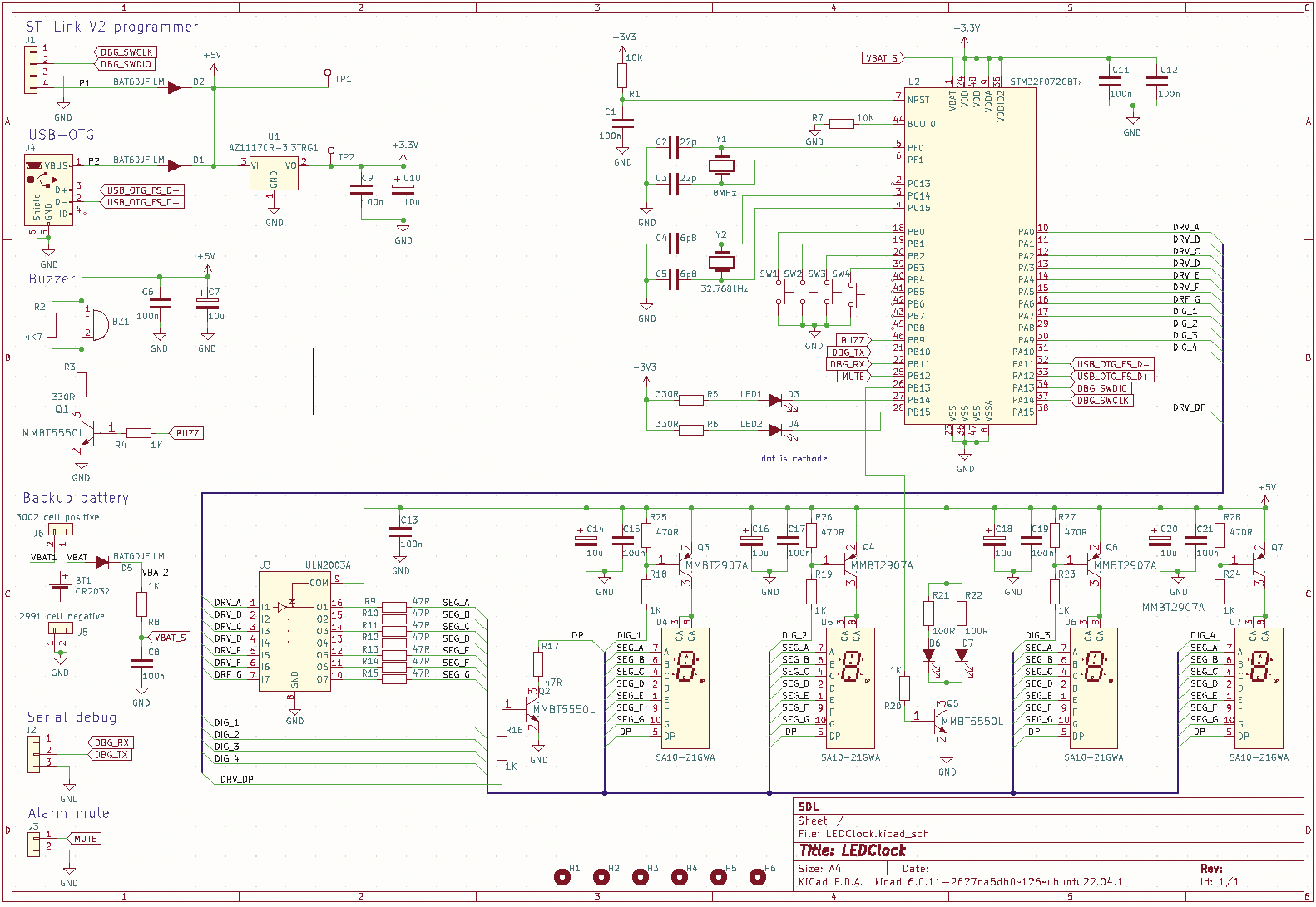
Once the PCB design was complete in KiCad, a 3D model of the PCB assembly was exported into FreeCAD, and an assembly of the case and front panel was created to ensure all the assumptions about dimensions were correct. The full schematic for the final design is shown in Figure 1.
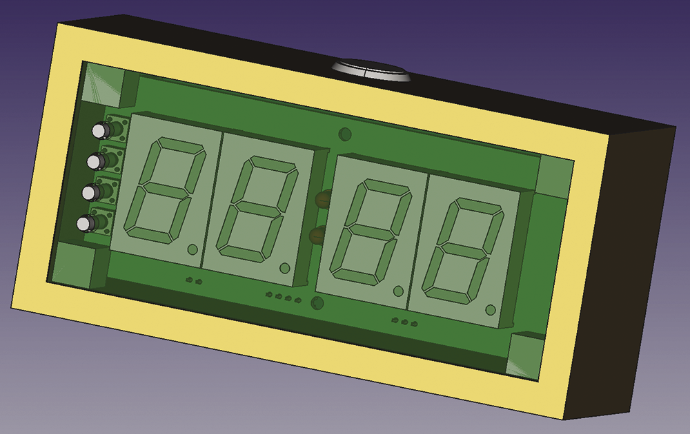
The 3D model (Figure 2) ensured mechanical dimensions matched and provided drawings for the manufacture of the front panel and dimensions for the wooden case. The PCB assembly can be seen behind the transparent front panel and the alignment of push-buttons with the holes in the front panel can be seen.
Firmware
The real-time clock feature of the STM32 family of microcontrollers is central to the firmware design. Much like the real-time clock found in every PC, it provides a convenient record of the current time in hours, minutes, and seconds (although seconds are not used in this design) and runs even when the unit is powered down, as long as backup power is provided from a button cell. The time is set with two of the buttons on the front panel. When the upper button is pressed, the time increments by a minute. If the button is held down, the time advances at one minute every half second. The lower button operates in a similar manner, but decrements the time. The alarm is set in the same way, whilst holding down the button on the top of the unit to cancel the alarm.
Seven-Segment Displays
Seven-segment displays are generally used only to display numeric characters, although a small subset of the alphabet is also possible. In this case, only numbers are required. The means to turn the numbers 0 to 9 into the correct pattern for the seven segments is easily achieved with a lookup table (Listing 1).
Listing 1: Number Lookup Table
// digit (0 to 9) to seven‑segment pattern
// 1 in binary constant means segment on
// 0 means segment off
static uint8_t  patterns[16] =
{
    //ABCDEFG (segment id)
    0b1111110, // 0
    0b0110000, // 1
    0b1101101, // 2
    0b1111001, // 3
    0b0110011, // 4
    0b1011011, // 5
    0b1011111, // 6
    0b1110000, // 7
    0b1111111, // 8
    0b1111011, // 9
    0b0000000, // blank
    0b0000000, // blank
    0b0000000, // blank
    0b0000000, // blank
    0b0000000, // blank
    0b0000000, // blank
};

/** write to selected digit */
static void write_digit(int digit)
{
  // extract the required pattern by using
  //the number as an index into the lookup table
  uint8_t pattern = patterns[digit & 0x0f];

  HAL_GPIO_WritePin(SEG_G_GPIO_Port, SEG_G_Pin, (pattern >> 0 & 1));
  HAL_GPIO_WritePin(SEG_F_GPIO_Port, SEG_F_Pin, (pattern >> 1 & 1));
  HAL_GPIO_WritePin(SEG_E_GPIO_Port, SEG_E_Pin, (pattern >> 2 & 1));
  HAL_GPIO_WritePin(SEG_D_GPIO_Port, SEG_D_Pin, (pattern >> 3 & 1));
  HAL_GPIO_WritePin(SEG_C_GPIO_Port, SEG_C_Pin, (pattern >> 4 & 1));
  HAL_GPIO_WritePin(SEG_B_GPIO_Port, SEG_B_Pin, (pattern >> 5 & 1));
  HAL_GPIO_WritePin(SEG_A_GPIO_Port, SEG_A_Pin, (pattern >> 6 & 1));
}
Timers
The clock firmware relies heavily on timers internal to the microcontroller. These timers count cycles of the system clock (in this case, 48MHz) and generate an interrupt when a specified target is reached. In most cases the timers are programmed to reload the same target, resulting in periodic interrupts.
The first timer has a one-second period used to toggle the display colon on or off, giving the clock a live feel, because the time only changes once a minute. The timer also reads the latest time (to the nearest second) from the real-time clock and saves it in a variable accessible by the display multiplexer. The display multiplexer (see the “Multiple Displays on a Single Bus” box for details) itself uses a timer, which is set in pulse width modulation (PWM) mode, generating a periodic interrupt at the multiplexing rate (20ms), used to move to the next digit and update its data.
Driving four seven-segment displays directly from the microcontroller would require at least 36 pins and 32 driver channels (if you include the decimal point) and would require a much larger microcontroller, four eight-channel driver chips, and a considerably more complex PCB layout. The driver chips are required because the microcontroller cannot sink sufficient current to light the LEDs). The usual solution is multiplexing, that is, to connect the cathodes in all the matching segments in each display together and to a low-side driver and the common anodes to high-level switches.
Each display is turned on in turn by these high-level switches whilst the correct seven-segment pattern is applied to the low-side driver. Therefore, each display is on for a maximum of one-quarter of the time, but by setting the LED current to an appropriate level, it’s quite possible to provide a display that is clearly visible in daylight. This setup requires 12 I/O pins, four high-side transistors, and a single low-side driver chip. An excellent description of display multiplexing is described on Wikipedia.
A second interrupt is generated at the end of the PWM period (less than or equal to the 20ms multiplexing rate) and switches off the current digit. In this way, if the PWM period is less than the multiplexing period, each display will be off for more than a quarter of the total time, causing the display to be dimmer. In this way, the PWM is used to control display brightness.
The clock has five push-buttons used to set the time, set or cancel an alarm, and control the display brightness. Four of these buttons are on the front panel adjacent to the display. They are connected to microcontroller I/O pins configured to generate interrupts when the push-button is pressed or released. Unfortunately, most push-buttons (and switches in general) do not change state cleanly but “bounce” between open and closed for several milliseconds before settling to the new state. This bounce can cause all sorts of weird effects if not dealt with, and push-button debouncing is a common problem often fixed in firmware with debouncing techniques. In this case, a timer is used for this function (see the “Debouncing Push-Buttons with Timers” box for details).
Push-buttons and switches rarely exhibit ideal behaviour: You would like them to go from open to closed in an instant. In reality, most exhibit what is known as switch bounce. De-bouncing switches can be achieved in many ways, some of which require extra hardware (resistor-capacitor (RC) networks, set-reset latches, etc.). However, in a microcontroller environment timers are often seen as a simple solution when a delay of a few tens of milliseconds is acceptable.
The operation goes like this: The microcontroller is set up to produce an interrupt once the button is pushed. At this point the state of the switch is recorded, and a 20ms timer is started. When the timer expires, the state is recorded again. If the two states are equal, a switch event is deemed to have occurred. If the switch “flapped” between states in the intervening 20ms, those transitions must be ignored. Thus, it is important not to resample the switch state while the 20ms timer is running, so the interrupt routine that does the initial sampling must either be disabled in that period or contain some logic that has a similar effect (Listing 3).
The push-buttons used to control the clock have varying functions depending on context: You need to differentiate between a brief push and a sustained press, the latter used to advance the clock rapidly when setting the time and alarm. Again, a timer is used – in this case, in one-shot mode. The timer is set when a button push is detected, and if, when the timer’s interrupt fires, the push-button is still pressed, the “sustained hold” function is initiated.
Finally, a timer is used to generate a 1KHz square wave to drive the buzzer. The timer interrupts every half-cycle (500µs), and the buzzer I/O pin state is toggled. The number of toggles is counted, and the toggling is controlled in such a way as to produce bursts of 1KHz sound at regular intervals – not quite enough to raise the dead, but a gentle reminder that it’s time to get up! One of the five push-buttons is a large circular type on the top of the clock case; pressing that button cancels the alarm.
Software Development
I know the use of integrated development environments (IDEs) can be controversial and very much a matter of taste, and it’s certainly possible to do this type of microcontroller development without one. The ARM compilers and standard libraries can be downloaded from your distro’s repository, and you’re off, with the use of any editor that suits you and make or cmake, again, at your choice. Once you have a compiled binary, ST-Link utilities allow you to program your device, and you can use the gbd utility to debug your program. If you don’t want to use the hardware abstraction layer (HAL) libraries provided by ST, you can generate your own header files with the addresses of the microcontroller registers and all the bit patterns required for configuration.
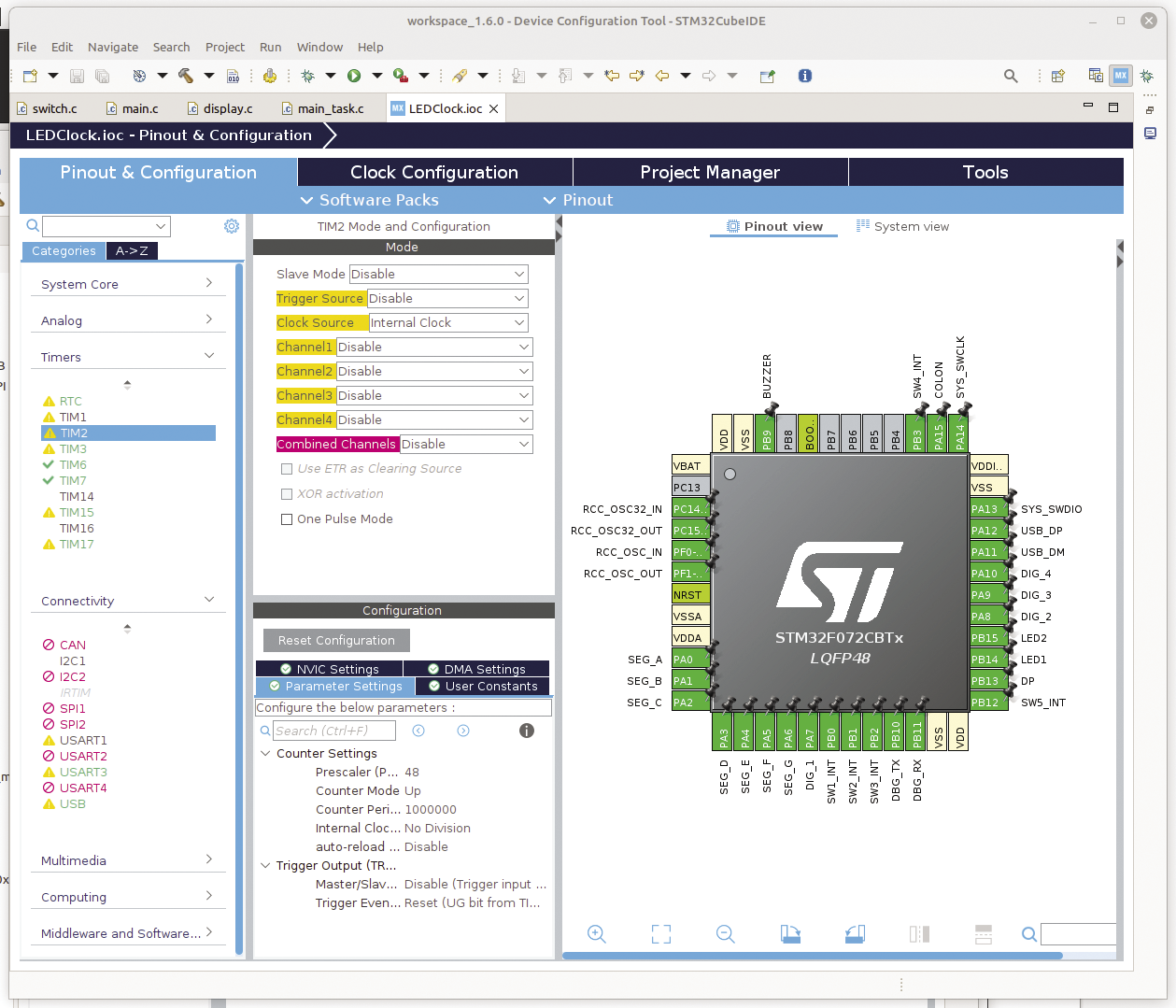
That said, ST’s STM32CubeIDE (Figure 3), which is based on Eclipse, does streamline the process by integrating ST’s CubeMX tool, a utility that lets you configure your microcontroller and generate a software framework that does all the initialization and leaves you with a blank main() function, to which you add your own code. You can label the pins of the microcontroller (bonus points if you use the same names as on the schematic!).
The HAL libraries hide a lot of the complexity of setting up some of the peripherals, but they are not perfect and so must be used with caution. Lots of resources online show how to use the IDE to set up the clocks, UARTs, timers, USB ports, and the like on an STM32 processor, including ST’s own getting started guide.
Once saved, the IDE then generates a set of #define lines for the I/O pins that you can use in your code, as well as a complete set of initialization routines. At this point, you can continue to use the IDE or ignore it and use make with the generated Makefile. However, if you stay with the IDE and have your hardware connected by an ST-Link programmer, a single mouse click in the IDE on the Run menu will compile, download, and run your code. This level of pre-configuration (including, if you want, the inclusion of a real-time operating system (RTOS) such as FreeRTOS) can leave you free to concentrate on your application code. In a commercial environment, time-to-market is everything, and time savings like this can be invaluable.
Redirecting stdin and stdout
Adding printf() statements to code is a time-honoured and useful debugging technique. In the STM32 environment, redirecting the printf() output to a serial port is straightforward; it then can be connected to a terminal emulator (e.g., Minicom) running on a laptop.
The low-level _write() function is defined in an STM32 library. The default implementation calls __io_putchar() in the C standard library, and in the embedded version of the library, the data goes to the equivalent of /dev/null.
The default _write() has weak attributes, which means it can be overridden by an alternative implementation simply by providing a replacement function with the same signature without the weak attribute (Listing 2).
Listing 2: Overriding Defaults
01 // the default implementation (in syscalls.c)
02 __attribute__((weak)) int _write(int file, char *ptr, int len)
03 {
04     ...
05 }
06
07 // the replacement to redirect output to a UART serial device.
08 int _write(int file, char *ptr, int len)
09 {
10     ...
11   HAL_UART_Transmit(&huart3, ptr, 1, ‑1);
12     ...
13 }
Once implemented, the full formatting power of printf() is available to output data to an external terminal. A similar technique can be applied to reading data from the terminal with getchar() or scanf():
// read from serial port
int _read(int file, char *data, int len)
{
  uint8_t ch;
  HAL_UART_Receive(&huart3, &ch, 1, -1);
  return 1;
}
Listing 3: Debouncing Switches
01 static bool timer_running = false;
02 static bool last_switch1_state = 1;
03
04 // interrupt callback called when a switch is pushed
05 void interrupt_callback(void)
06 {
07   if(!timer_running)
08   {
09     last_switch1_state = read_pin();
10   }
11
12   // start a timer to wait for 20ms
13   // then resample in timer ISR. only
14   // act if the two samples match
15   timer_running = true;
16
17   register_timer_callback(timer_callback);
18   start_timer();
19 }
20
21
22 // debounce switch: if state is still same
23 // as initial after 20ms confirm action
24 void timer_callback(void)
25 {
26   stop_timer();
27   bool switch1_state = read_pin();
28
29   if(switch1_state == last_switch1_state)
30   {
31     // switch push verified, do required action
32   }
33 }
Software Summary
Unlike many command-line programs running on Linux or any other OS, nothing much happens in the main() of much embedded firmware, and in the present case, once the appropriate timers have been started and interrupt handlers registered, main() simply enters an idle loop. Hardware initialization has occurred in code generated by the IDE before main() is called, according to the device configuration shown in Figure 3, and in other settings in the IDE. The timers handle the display refresh and multiplexing, and the interrupt service routines are called when the push-buttons are pressed to change the time, set the alarm, cancel the alarm, or change the display brightness. That’s it!
The Completed Unit
I used FreeCAD to design an enclosure for the completed unit with the use of a STEP file of the PCB assembly exported from KiCAD, to ensure a good fit and calculate the locations of fixing holes and the like. Although the case was made by hand from wood, as described below, the 3D model ensured I was able to cut the required pieces correctly the first time, eliminating wasted time and materials. The 3D model was also very useful in simply visualizing the finished item.
FreeCAD is another open source package, and every time I return to it, I find the developers have taken another step in increasing its functionality. It really is an exemplary open source project.
Construction
The front panel of the unit is a 3mm-thick piece of green-tinted Perspex, and the PCB with all the displays and other components are mounted directly behind this acrylic sheet. The PCB was manufactured with a black solder resist (mask) to avoid it being visible. The green tint does a good job of hiding the internals whilst letting through the green LED light.
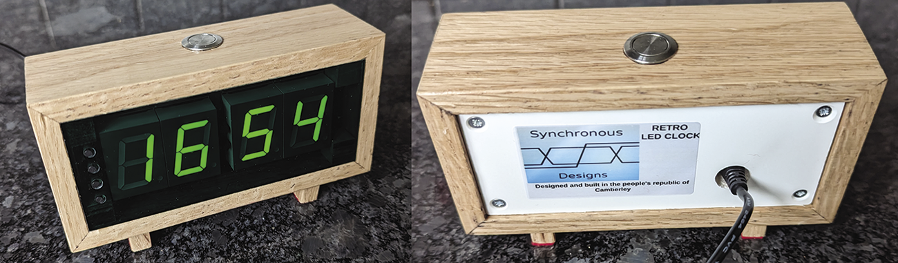
The case is very simple (Figure 4). I wanted a real wood case for a retro feel. It’s cut from a strip of oak 50mm wide and 8mm thick (2 inches by 5/16 inch for my American friends). The four sides are cut at an angle of 45 degrees to form mitred joints and glued together. Small wooden blocks are glued internally for mounting the PCB, and the front panel is a simple friction fit into the aperture. The back panel is a similar piece of opaque white Perspex fitted to the PCB with stand-offs. It has holes for mounting screws and a larger aperture to allow the micro-USB plug to pass through to the PCB-mounted USB socket.
The wooden case has a hole drilled in the top to receive the alarm cancel button. Small wooden feet are cut at an angle from an off-cut of the same wood, to set the clock at a slight upward tilt. Clear varnish protects the wood and completes the retro look. The dimensions were taken from the 3D model, which again proved invaluable in eliminating any nasty surprises.
Wrap Up
This clock was a fun project: Once built, it is not dependent on any other equipment but is a useful object in its own right. I know these days there’s always a phone to tell the time, but once you look at your phone, you can be drawn into your day rather than turning over and going back to sleep! This clock is clearly visible from my beside cabinet without raising my head, and with the display dimmed, it does not flood the room with light. I think the retro look is quite pleasing, but that’s a matter of taste, of course. I’ve made a few of these clocks to give as gifts, and it will be interesting to see how they are received. The completed design, both hardware and software, can be found at my GitHub page.