
Home Sweet Home
Automating your four walls does not necessarily require commercial solutions. With a little skill, you can develop your own projects on a low budget.
Home automation offers many opportunities, but equally harbors many risks. If you succeed in becoming independent of commercial products, you can save money while retaining control over what data flows where. In this case, the Message Queuing Telemetry Transport (MQTT) protocol proves to be very useful.
A previous article on Z-Wave showed how you can bring the Raspberry Pi up to speed with Home Assistant and components available on the market to attain the goal of achieving automation magic in your home without human interference. Plenty of components can be addressed by Home Assistant, even without the cloud. The only limits are your wallet and your imagination.
This sequel explains how you tweak both the price and the DIY factors of the components. The Raspberry Pi from model 3 onward comes with a wireless interface that is also available in many microcontroller modules and is likely to open many doors. The glue that connects the whole thing to the Home Assistant environment looked at in the previous article is an IP-capable protocol that saw the light of day long before any Internet of Things (IoT) hype did: MQTT.
The MQTT protocol was introduced in 1999 and is a text-based protocol that runs over TCP on any IP network. Transport Layer Security (TLS) can optionally be used for encryption. The sensors and actuators communicate as clients with the broker, which acts as the communications hub. Addressing relies on what are known as “topics.” Transmitters are referred to as publishers, and receivers as subscribers.
Testing MQTT
To implement the protocol on the Raspberry Pi, you first need the mosquitto package. For the small implementation tests that follow, you will also need the matching client. You can set up both components on the Raspberry Pi with the commands:
$ sudo apt-get install mosquitto
$ apt-get mosquitto-clients
If the broker is running after the install, you can log in to the individual topics with the client and retrieve a list of topics with a command-line call that specifies the host on which the broker is running with the -h option:
$ mosquitto_sub -h localhost -t "#"In this case, it is localhost. For example, to send the value 10 to a topic named test/test1 and receive the value as a subscriber, you would use the commands:
$ mosquitto_pub -V mqttv311 -h 192.168.3.7 -t test/test1 -m 10
$ mosquitto_sub -h 192.168.3.7 -t test/test1
For a more practical example, I’ll use MQTT to transfer the measured values of a one-wire temperature sensor of the DS18x20 type connected to a Raspberry Pi to the broker listening on another Raspberry Pi. To do this, you need to enable one-wire support up front with
dtoverlay=w1-gpioin the /boot/config.txt file.
After connecting the sensor to the standard one-wire GPIO port, the temperature values can be queried as four-digit integers in /sys/bus/w1/devices/28-0417c1b1f7ff/w1_slave. The value 28-0417c1b1f7ff is the unique ID of the sensor on the bus. The complete command sequence is:
$ mosquitto_pub -h 192.168.3.7 -t wohn/temp/28-0417c1b1f7ff -m $value
$ mosquitto_sub -h localhost -t wohn/temp/28-0417c1b1f7ff
To transfer the values to the Home Assistant environment, you need to enter the broker you are using in the configuration.yaml file; in this case, it is running on the same host (Listing 1, lines 1-2). The entries in the lines that follow take care of subscribing to the appropriate topic and fielding the sensor data in Home Assistant; the last line also specifies degrees Celsius as the unit.
Listing 1: configuration.yaml
01 mqtt:
02   broker: localhost
03
04 sensor:
05   ‑ platform: mqtt
06     name: temp1
07     state_topic: "living/temp/28‑0417c1b1f7ff"
08     unit_of_measurement: '°C'
ESP8266 Controller
The theoretical side is now covered, but to use a separate Raspberry Pi for each remote actuator or sensor seems a little unrealistic in practice. The ESP8266 controller will come in handy here. On the one hand, you can source low-priced and useful developer boards that use this controller; on the other hand, the chip is used in various products from the Far East, and you can take control of many of these simply by flashing them with freely available firmware.
For the tests here, I used a Sonoff Basic WiFi smart switch (Figure 1). This controllable relay switch has a screw connection for a 220V mains supply with switchable output.
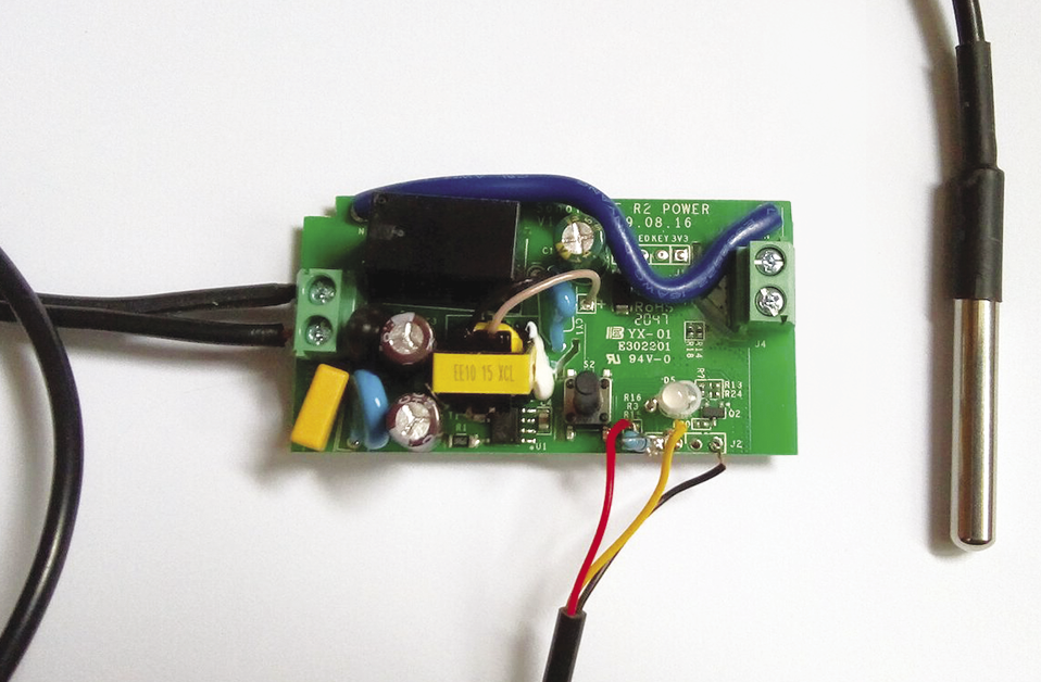
CAUTION: There is a danger to life if this hardware is not used correctly. In this article, I am restricting the supply voltage to the module to 3.3V.
The firmware is Tasmota. The software lets you configure a variety of supported sensors and components on the existing GPIO ports of the controller, such as the temperature sensor I referred to earlier. Tasmota uses MQTT to transmit the data from the sensors.
Flashing Tasmota
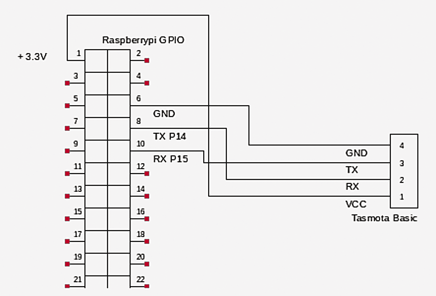
Among the several ways to flash Tasmota, one popular approach is to use a USB serial adapter. A description can be found on the Getting Started page of the project. Because the Raspberry Pi comes with a serial interface, I will do the flashing directly through the GPIO. The wiring required for this is shown in Figures 1 and 2. The esptool.py utility from the PiOS repository provides the software.
The Tasmota firmware, along with a massive collection of information, can be found in the project’s GitHub repository. I downloaded the sensor variant for the tests because I wanted to integrate the temperature sensor:
$ wget -c U
http://ota.tasmota.com/tasmota/release-9.4.0/tasmota-sensors.bin
After connecting the module as shown, you have to hold down the button on the Sonoff module while powering it on; the LED does not light up. Next, use the command
$ esptool --port /dev/ttyAMA0 chip_idto check whether you can access the Sonoff. An ID must be shown.
Finally, flash Tasmota with the command:
$ esptool --port /dev/ttyAMA0 write_flash -fm dout 0x0 tasmota-sensors.binThis operation should take about a minute. When the module is restarted, it reports for duty as the new WiFi access point, which you can reach at http://192.168.4.1 and on which you configure the WiFi network to be used. All further setup steps are then performed with the IP address assigned by your own WiFI network.
Setting Up Tasmota
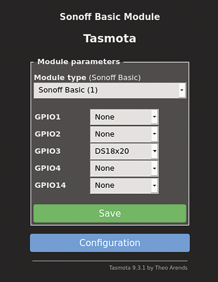
Before proceeding, you first need to connect the temperature sensor to one of the GPIOs used for flashing (RX/TX), which is now free. You can do this with a pull-up resistor and the 3.3V and GND connections. After wiring the elements, it’s time to configure the sensor; its name will have already appeared in the GUI (Figure 3).
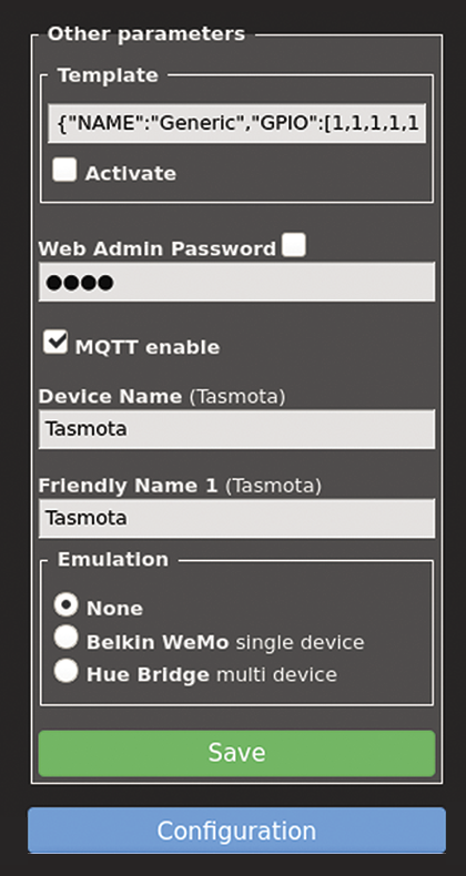
You also need to assign a password for the web GUI and activate MQTT (Figure 4), which you will be using to deliver the data to Home Assistant. The broker and topic are configured in the corresponding entries in the web interface, where you will also find the Tasmota console, which lets you issue commands directly and set up the parameterization.
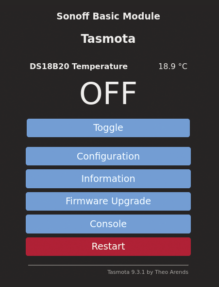
At this point at the latest, I recommend studying the very good documentation from Tasmota’s GitHub repository. For this project, I used a command that makes the later integration with Home Assistant by autodiscovery very easy by telling Tasmota to announce all available topics (setoption19 on). At the end of the day, Tasmota advertises itself in the GUI as a web switch with a temperature sensor (Figure 5). You can also view the MQTT publishing in the Console, if needed.
Integration
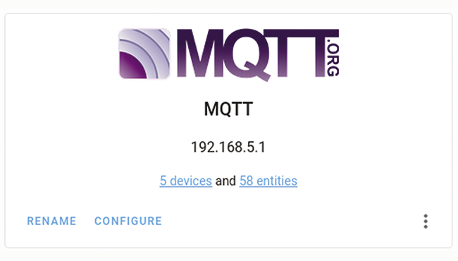
To make the components available in Home Assistant, you now need to set up MQTT integration in the GUI. To do so, all you need is the IP address and port of the broker you are using; by default, this is set to 1883. After the setup, the new MQTT devices should be displayed (Figure 6).
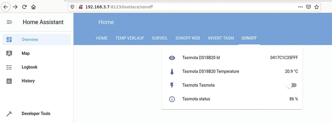
After clicking on the entities URL, both the switch and the temperature sensor are shown as available Home Assistant entities, and you can now use them in the usual way (Figure 7). In combination with the relay in the Sonoff module, the familiar automation features of Home Assistant can now be used to implement, say, a simple thermostat control.
Conclusions
The Tasmota option associated with Home Assistant’s autodiscovery of MQTT integration easily makes this DIY solution as convenient as the commercial counterparts described in the previous article. Homebrewing turns out to be worthwhile – and great fun, too.